
IOM SYSLOOP (IOM SL 01 S 3GB)


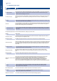
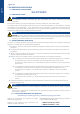
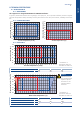
Table Of Contents
- CONTENTS
- 1. GENERAL RECOMMENDATIONS
- 2. INSPECTION AND STORAGE
- 3. WARRANTY
- 4. CONTENTS Of PACKAGE
- 5. DIMENSIONS
- 6. HANDLING
- 7. REFRIGERATION SPECIFICATIONS
- 8. TECHNICAL SPECIFICATIONS
- 9. ELECTRIC SPECIFICATIONS
- 10. INSTALLATION
- 11. DUCTING AND NOISE LEVEL REDUCTION
- 12. UNCLAMPING THE COMPRESSOR
- 13. HYDRAULIC LINKS
- 14. WIRING DIAGRAM AND LEGEND
- 15. ELECTRICAL CONNECTIONS
- 16. REGULATION
- 17. FINAL TASKS
- 18. STARTING - RECOMMENDATIONS - SETTINGS
- 19. MAINTENANCE AND SERVICING
- 19.1. FAULT FINDING
- 19.1.1. NEITHER THE FAN NOR THE COMPRESSOR OPERATE
- 19.1.2. VENTILATION (FAN) MODE OPERATES BUT THE COMPRESSOR DOES NOT OPERATE
- 19.1.3. INSUFFICIENT COOLING OR HEATING PRODUCTION
- 19.1.4. INSUFFICIENT WATER FLOW AT THE LEVEL OF THE COAXIAL EXCHANGER.
- 19.1.5. APPEARANCE OF WATER DROPLETS IN THE APPLIANCE
- 19.1.6. APPEARANCE OF ABNORMAL NOISES AND VIBRATIONS IN THE CASING
- 19.2. ALARM CODES
- 19.1. FAULT FINDING
- 20. IN CASE OF WARRANTY - MATERIAL RETURN PROCEDURE
- 21. ORDERING SERVICE AND SPARE PARTS ORDER
- DIMENSIONS
- CONFIGURATION R1.AI RECT/S4.AO RECT
- CONFIGURATION R2.AI RECT/S4.AO RECT
- CONFIGURATION R1.AI 1Ø200/S4.AO RECT OR R1.AI 1Ø200 FAØ100/S4.AO RECT OR R1.AI 1Ø200 FAØ125/S4.AO RECT
- CONFIGURATION R2.AI 1Ø200/S4.AO RECT OR R2.AI 1Ø200 FAØ100/S4.AO RECT OR R2.AI 1Ø200 FAØ125/S4.AO RECT
- CONFIGURATION R1.AI RECT/S4.AO 1Ø200 OR R1.AI RECT/S3.AO 1Ø200
- CONFIGURATION R2.AI RECT/S4.AO 1Ø200 OR R2.AI RECT/S3.AO 1Ø200
- CONFIGURATION R1.AI 1Ø200/S4.AO 1Ø200 OR R1.AI 1Ø200 FAØ100/S4.AO 1Ø200 OR R1.AI 1Ø200 FAØ125/S4.AO 1Ø200 OR R1.AI 1Ø200/S3.AO 1Ø200 OR R1.AI 1Ø200 FAØ100/S3.AO 1Ø200 OR R1.AI 1Ø200 FAØ125/S3.AO 1Ø200
- CONFIGURATION R2.AI 1Ø200/S4.AO 1Ø200 OR R2.AI 1Ø200 FAØ100/S4.AO 1Ø200 OR R2.AI 1Ø200 FAØ125/S4.AO 1Ø200 OR R2.AI 1Ø200/S3.AO 1Ø200 OR R2.AI 1Ø200 FAØ100/S3.AO 1Ø200 OR R2.AI 1Ø200 FAØ125/S3.AO 1Ø200
- CONFIGURATION AO XLN
- WIRING DIAGRAM
- DIMENSIONS
- CONFIGURATION R1.AI RECT/S4.AO RECT
- CONFIGURATION R2.AI RECT/S4.AO RECT
- CONFIGURATION R1.AI 1Ø200/S4.AO RECT OU R1.AI 1Ø200 FAØ100/S4.AO RECT OU R1.AI 1Ø200 FAØ125/S4.AO RECT
- CONFIGURATION R2.AI 1Ø200/S4.AO RECT OU R2.AI 1Ø200 FAØ100/S4.AO RECT OU R2.AI 1Ø200 FAØ125/S4.AO RECT
- CONFIGURATION R1.AI RECT/S4.AO 1Ø200 OU R1.AI RECT/S3.AO 1Ø200
- CONFIGURATION R2.AI RECT/S4.AO 1Ø200 OU R2.AI RECT/S3.AO 1Ø200
- CONFIGURATION R1.AI 1Ø200/S4.AO 1Ø200 OU R1.AI 1Ø200 FAØ100/S4.AO 1Ø200 OU R1.AI 1Ø200 FAØ125/S4.AO 1Ø200 OU R1.AI 1Ø200/S3.AO 1Ø200 OU R1.AI 1Ø200 FAØ100/S3.AO 1Ø200 OU R1.AI 1Ø200 FAØ125/S3.AO 1Ø200
- CONFIGURATION R2.AI 1Ø200/S4.AO 1Ø200 OU R2.AI 1Ø200 FAØ100/S4.AO 1Ø200 OU R2.AI 1Ø200 FAØ125/S4.AO 1Ø200 OU R2.AI 1Ø200/S3.AO 1Ø200 OU R2.AI 1Ø200 FAØ100/S3.AO 1Ø200 OU R2.AI 1Ø200 FAØ125/S3.AO 1Ø200
- CONFIGURATION AO XLN
- SCHEMAS ELECTRIQUES
- ABMESSUNGEN
- KONFIGURATION R1.AI RECT/S4.AO RECT
- KONFIGURATION R2.AI RECT/S4.AO RECT
- KONFIGURATION R1.AI 1Ø200/S4.AO RECT ODER R1.AI 1Ø200 FAØ100/S4.AO RECT ODER R1.AI 1Ø200 FAØ125/S4.AO RECT
- KONFIGURATION R2.AI 1Ø200/S4.AO RECT ODER R2.AI 1Ø200 FAØ100/S4.AO RECT ODER R2.AI 1Ø200 FAØ125/S4.AO RECT
- KONFIGURATION R1.AI RECT/S4.AO 1Ø200 ODER R1.AI RECT/S3.AO 1Ø200
- KONFIGURATION R2.AI RECT/S4.AO 1Ø200 ODER R2.AI RECT/S3.AO 1Ø200
- KONFIGURATION R1.AI 1Ø200/S4.AO 1Ø200 ODER R1.AI 1Ø200 FAØ100/S4.AO 1Ø200 ODER R1.AI 1Ø200 FAØ125/S4.AO 1Ø200 ODER R1.AI 1Ø200/S3.AO 1Ø200 ODER R1.AI 1Ø200 FAØ100/S3.AO 1Ø200 ODER R1.AI 1Ø200 FAØ125/S3.AO 1Ø200
- KONFIGURATION R2.AI 1Ø200/S4.AO 1Ø200 ODER R2.AI 1Ø200 FAØ100/S4.AO 1Ø200 ODER R2.AI 1Ø200 FAØ125/S4.AO 1Ø200 ODER R2.AI 1Ø200/S3.AO 1Ø200 ODER R2.AI 1Ø200 FAØ100/S3.AO 1Ø200 ODER R2.AI 1Ø200 FAØ125/S3.AO 1Ø200
- KONFIGURATION AO XLN
- STROMLAUFPLANS
- DIMENSIONI
- CONFIGURAZIONE R1.AI RECT/S4.AO RECT
- CONFIGURAZIONE R2.AI RECT/S4.AO RECT
- CONFIGURAZIONE R1.AI 1Ø200/S4.AO RECT O R1.AI 1Ø200 FAØ100/S4.AO RECT O R1.AI 1Ø200 FAØ125/S4.AO RECT
- CONFIGURAZIONE R2.AI 1Ø200/S4.AO RECT O R2.AI 1Ø200 FAØ100/S4.AO RECT O R2.AI 1Ø200 FAØ125/S4.AO RECT
- CONFIGURAZIONE R1.AI RECT/S4.AO 1Ø200 O R1.AI RECT/S3.AO 1Ø200
- CONFIGURAZIONE R2.AI RECT/S4.AO 1Ø200 O R2.AI RECT/S3.AO 1Ø200
- CONFIGURAZIONE R1.AI 1Ø200/S4.AO 1Ø200 O R1.AI 1Ø200 FAØ100/S4.AO 1Ø200 O R1.AI 1Ø200 FAØ125/S4.AO 1Ø200 O R1.AI 1Ø200/S3.AO 1Ø200 O R1.AI 1Ø200 FAØ100/S3.AO 1Ø200 O R1.AI 1Ø200 FAØ125/S3.AO 1Ø200
- CONFIGURAZIONE R2.AI 1Ø200/S4.AO 1Ø200 O R2.AI 1Ø200 FAØ100/S4.AO 1Ø200 O R2.AI 1Ø200 FAØ125/S4.AO 1Ø200 O R2.AI 1Ø200/S3.AO 1Ø200 O R2.AI 1Ø200 FAØ100/S3.AO 1Ø200 O R2.AI 1Ø200 FAØ125/S3.AO 1Ø200
- CONFIGURAZIONE AO XLN
- SCHEMA ELETRICO
- DIMENSIONES
- CONFIGURACIÓN R1.AI RECT/S4.AO RECT
- CONFIGURACIÓN R2.AI RECT/S4.AO RECT
- CONFIGURACIÓN R1.AI 1Ø200/S4.AO RECT O R1.AI 1Ø200 FAØ100/S4.AO RECT O R1.AI 1Ø200 FAØ125/S4.AO RECT
- CONFIGURACIÓN R2.AI 1Ø200/S4.AO RECT O R2.AI 1Ø200 FAØ100/S4.AO RECT O R2.AI 1Ø200 FAØ125/S4.AO RECT
- CONFIGURACIÓN R1.AI RECT/S4.AO 1Ø200 O R1.AI RECT/S3.AO 1Ø200
- CONFIGURACIÓN R2.AI RECT/S4.AO 1Ø200 O R2.AI RECT/S3.AO 1Ø200
- CONFIGURACIÓN R1.AI 1Ø200/S4.AO 1Ø200 O R1.AI 1Ø200 FAØ100/S4.AO 1Ø200 O R1.AI 1Ø200 FAØ125/S4.AO 1Ø200 O R1.AI 1Ø200/S3.AO 1Ø200 O R1.AI 1Ø200 FAØ100/S3.AO 1Ø200 O R1.AI 1Ø200 FAØ125/S3.AO 1Ø200
- CONFIGURACIÓN R2.AI 1Ø200/S4.AO 1Ø200 O R2.AI 1Ø200 FAØ100/S4.AO 1Ø200 O R2.AI 1Ø200 FAØ125/S4.AO 1Ø200 O R2.AI 1Ø200/S3.AO 1Ø200 O R2.AI 1Ø200 FAØ100/S3.AO 1Ø200 O R2.AI 1Ø200 FAØ125/S3.AO 1Ø200
- CONFIGURACIÓN AO XLN
- ESQUEMA ELECTRICO

English
8 SYSLOOP
The unit is not designed to withstand weights or stresses from adjacent equipment, pipe work or
constructions. Any foreign weight or stress on the unit structure could lead to a malfunction or a
collapse with dangerous consequences for personnel and property. In such an event, the warranty
shall be null and void.
Caution
9. ELECTRIC SPECIFICATIONS
A variance of ±10% is acceptable in relation to the operating voltage marked on the appliance’s Maker’s
Plate.
Operating voltages:
² 230V / 1 ph / 50 Hz (207 Volts minimum; 253 Volts maximum.)
Comments: the stated voltages represent the accepted range. However, certain components may be subject
to premature wear on appliances operating continuously, for extensive periods, on abnormally low or high
voltages.
9.1. ELECTRICAL POWER SUPPLY
10. INSTALLATION
10.1. GENERALITIES
1. To avoid any damage, this equipment must not be used to supply heating or cooling during building
work.
2. Check that the voltage, the number of phases and the capacity of the unit comply with the
installation plans.
3. Check the size of the unit in relation to the plans to ensure that the unit will be installed in the right
location.
4. After having removed the packing box, take out the suspension kit that is to be found inside the fan
outlet frame.
5. Before installing the unit, check its height in relation to the available free ceiling height.
6. Take particular care over the location and routing of the water pipes and the condensate drainage
pipe as well as the electrical wiring. The location and routing of these items must be clearly indicated
on the plans.
7. It is always advisable for the heat pump installer to consult with all the various entrepreneurs
responsible for the pipe work, partitioning, ceiling and electrical installation on the site.
8. If necessary, change the direction of the airow inlet from the front to the side of the appliance,
or vice versa, prior to installing the unit in the ceiling. Refer to the instructions detailed in § AIR
DISCHARGE MODIFICATION, page 12.
9. We advise the installer to cover the appliances with a plastic sheet to protect it during the nal
building work.
This is particularly important if work such as spraying the joists with re retardant, sanding, spray
painting and plastering has not been completed.
MODELS
Fuse aM
(without
heating)
Full load current
(max)
(without heating)
Fuse aM
(with heating)
Full load current
(max)
(with heating)
Starting
amperage
230V
SL15
6A aM 4.8A 10A aM 8.7A 17.4A
SL20
6A aM 5.5A 12A aM 10.8A 21.2A
SL30
8A aM 6.93A 16A aM 12.9A 23.4A