
SYSHRW Engineering Data Manual (EDM HRW S 4GB)


SYSHRW
2
Technical Specications
Introduction
The new generation of SYSHRW model reversible water source heat
pumps is the fruit of our considerable product experience and our
awareness of the market, all combined with a technology based on
the energy efciency of machines, in order to provide a market offer
for units with the highest performance in terms of COP.
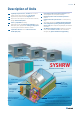
Range
The SYSHRW horizontal units are designed for installation in specically
designed false ceilings or in technical rooms, and are available with a
range of nominal cooling capacity ratings of between 5.3 and 30.0
kW, with 10 models based on 4 different case sizes.
Operating range
To enable a much wider operating range and operation using a water
source in an application with a dry cooler, the standard SYSHRW units
are designed to operate in a water source temperature range of
between 13 and 48 °C (according to the models).
Casing design
The casing is made of galvanised sheet steel. To facilitate access to
the main components, wide removable panels provide access to the
compressor, the fan and the electronic control box.
The condensate drain pan has anti-corrosion treatment consisting of
oven-baked epoxy paint.
The inside of the casing, on the fan compartment side, is coated with
closed cell polyurethane foam thermal-acoustic insulation; this lagging
is 15 mm thick and is classied M1. On the compressor compartment
side, the thermal-acoustic insulation consists of Isofeutre felt, 15 mm
thick (except on models 096 and 120).
Filtration
All units (except for models 096 & 120 supplied with G2-M1 lter) are
factory equipped with a G2-M3 disposable air lter, 20 or 25 mm thick,
according to the models. Optionally, the units can be tted with G2-M1
or G3-M1 lter. The lter can be removed/installed from the side of
the units without plenum and from the side or from the bottom of the
units equipped with plenum, without having to remove the optional
return duct.
Hydraulic connections
The water source outlet and return connectors are located on the
outside of the unit, on the compressor compartment side. They are
female gas type tapped ttings 3/4" or 1"1/4 (male), according to the
models. The condensate evacuation connection is of the smooth tube
type, with an outside diameter of 19 mm for models 019 to 072, 22
mm for models 096 and 120.
Electronic control box
The electrical box is located inside the compressor compartment.
A wide access panel is provided to facilitate the maintenance
operations.
The electrical power supply required for model 019 is 230 V / 1 Ph /
50 Hz, whereas models SYSHRW 027 to 120 require 400 V / 3 Ph / 50
Hz + neutral. The compressors are factory equipped with an internal
thermal protection with an automatic reset function.
Refrigerant circuit
The refrigerant circuit comprises a scroll or rotary type hermetic
compressor, a cycle reversal valve, a water/refrigerant heat exchanger,
a liquid receiver, a bi-ow thermostatic expansion valve and a nned
coil.
The refrigerant circuit also comprises an HP pressure switch with
manual reset (range 28-20 bar) and an LP pressure switch with an
automatic reset function (range 1.4-2.4 bar). Two Shrader valves (HP
& LP) are available for pressure measurement on the refrigerant circuit.
The water/refrigerant heat exchanger is of the brazed stainless steel
plate type, for increased efciency. The anti-freeze safety of the heat
exchanger is provided , on the one hand, by a water pipe sensor
located on the water outlet of the unit and, on the other hand, by a
water ow protection monitored by the electronic board. Maximum
service pressure is 31 bar. The heat exchangers are particularly well
adapted to the operation of reversible heat pumps which have high
thermal transfer rates for a low water ow-rate.
The air/refrigerant coil is made up of aluminium ns which are
mechanically crimped onto copper tubes. The geometry of the coil and
of the n prole have been carefully designed to provide maximum
efciency in the operation of the units.
The cycle reversal valve is designed to be normally energised in
heating mode. This logic enables the heat pump to continue to operate
in cooling mode if this valve fails.
The liquid receiver enables the charge of HFC 407C refrigerant to be
optimised, particularly in cooling mode, in order to maintain a high
COP value.
A Bi-Flow expansion valve ensures and enables a wide operating
range with water inlet temperatures which can vary between 13 °C
and 48 °C (according to the models) at the minimum or maximum
ow-rate.
Ventilation section
The fan compartment contains the fan-motor assembly, the air/
refrigerant coil and the condensate drain pan. The ventilation section
is completely isolated from fan compartment by a thermally and
acoustically insulated partition wall.
Wide removable panels provide access to the various internal
components. The condensate drain pan has an anti-corrosion
treatment and comprises a oat-type safety device to prevent
accidental overow of the pan.
The sizes 019 to 072 are equipped with a 3 speed direct-drive
fan motor with ipsothermal protection against overheating during
operation. The motor ipsothermal protection fault is displayed in the
form of a coded signal on the LED of the STORM 2 electronic board.
The 3 fan speeds can be controlled either manually or automatically by
the electronic management board of the unit. The fan-motor assembly
is mounted on an independent chassis which is isolated from the
casing by anti-vibration mounts.
Belt type drive with variable pitch pulley is supplied on models 096
and 120.
In the standard conguration, the fan blows straight in line with the
air intake. The perpendicular blowing option is available on all units
by switching the side panels and the fan-motor assembly.
Suspension kit
In order to facilitate installation on site, a suspension kit consisting
of rubber blocks and washers is supplied with the units (except for
models 096 and 120).
Optional features
Wired main disconnect switch to be installed on the
casing,
Electric heater at discharge side,
General alarms fault report,
Motorized water valve supplied loose.