
HandBook F R60K2022 07 11

31/59 | F-R60K
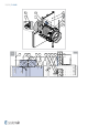
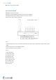
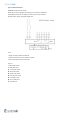
Installation OUT of the Shaft Wall
One Side Gypsum Covered Wall - 2 Layers
1. The supporting construction opening must be prepared as depicted in wall preparation. Opening surfaces must be
even and cleaned off.
2. The opening dimension D1 is driven by the nominal dimensions of the damper with added clearance. The flexible
wall opening must be reinforced as per the shaft plasterboard walls manufacturer instructions (usually only top
and bottom horizontal metal beam).
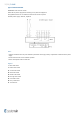
3. Place the duct into the opening and onto the load bearing structure (hangers) in such a way that the duct will stick
out of the wall to the needed distance.
4. Press the insulation (F3) for filling the opening around the duct and cut its edges to even it with the wall surface.
5. Fix the duct to a suitable sheet metal ringlet accessory (A1) or UVH30/Lindab ringlet at the wall surface. Then fix
the ringlet through L-profile (F5) to the supporting construction with screws (F1).
6. Insert the damper into the duct and fasten through the duct that crosses the wall with screws (F6). Make sure the
fixing screws are not interfering with the blade movement.
7. Place two threaded rods (F7) through the suitable sheet metal ringlet (accessory) or UVH30 ringlet.
8. Hang the damper weight and connected duct directly after the damper insulating ring also with nuts (F8).
9. Paint the insulation surface in alignment with the wall with a suitable glue (F2) up to 100 mm from the duct to
cover the insulation and part of the wall.
10. Insulate the duct parts between the damper and the wall with one layer of insulation (F8). For easier fixing, the
duct insulation should overlap the dampers’ insulation ring at least 20 mm.
11. Entwine the insulation. Secure the insulation with a binding wire (d=1,6 mm) in the standard way that is applied
when insulating circular ducts or by using wire clamps to sew together the meshes on the top of the insulation (F8).
12. Compress the overlapping insulation while applying aluminium tape (F9) to fix the insulation to the damper ring.
The actuator and thermal sensor must remain uninsulated and without tape for future maintenance.
13. If needed, uncover and clean the damper after installation.
14. Make sure the fixing screws are not interfering with the blade movement and check the damper’s functionality.
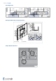
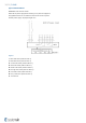
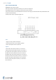
Installation Distances
For installation Out of the wall, the minimum distance from the wall or ceiling to the damper body is 100 mm. For
multiple crossings through a fire resistive wall the minimum distance between the duct opening is 200 mm. This
applies for distances between the duct holding the damper and a nearby foreign object crossing the fire-resistive wall.
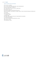
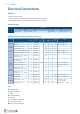
OUT
F-R60K
DN100 ... DN630
EI 60 (v
e
- i ↔ o) S
d)
360°
≥ 80 mm
Notes:
d) - Shaft wall - one side covered with 2 layers of gypsum board
v
e
- Vertical wall placement