
HandBook F R60K2022 07 11


13/59 | F-R60K
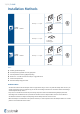
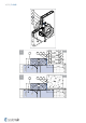
Installation Methods
ON
F-R60K
DN100 ... DN630
EI 60 (v
e
- i ↔ o) S
a) b)
360°
≥ 100 mm ≥ 100 mm
d)
≥ 80 mm
EI 60 (h
o
- i ↔ o) S
c)
≥ 100 mm
≥ 620 kg/m
3
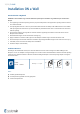
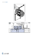
OUT
F-R60K
DN100 ... DN630
EI 60 (v
e
- i ↔ o) S
a) b)
360°
≥ 100 mm ≥ 100 mm
d)
≥ 80 mm
Notes:
a) - Flexible (plasterboard) wall
b) - Concrete/masonry/cellular concrete (rigid) wall
c) - Concrete/cellular concrete (rigid) floor/ceiling
d) - Shaft wall - one side covered with 2 layers of gypsum board
v
e
- Vertical wall placement
h
o
- Horizontal floor/ceiling placement
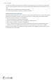
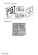
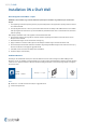
Installation Rules
• The duct connected to the fire damper must be supported or hung in such a way that the damper does not carry its
weight. The damper must not support any part of the surrounding construction or wall which could cause damage
and consequent damper failure.
• Easy access to mechanism and internal parts during inspection must be considered during damper placement.
• According to the standard EN 1366-2, the distance between the fire damper bodies must be at least 200 mm.
• The distance between the adjacent wall/ceiling and the damper must be at least 75 mm.
• When the damper is installed into a fire partition structure, it must be placed so that the damper blades in its closed
position are located inside this structure.