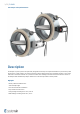
F-R60K Fire Damper with Quick Mount Kit Handbook
/59 | F-R60K Table of Contents Overview . . . . . . . . . . . . . . . . . . . . . . . . . . . . . . . . . . . . . . . . . . . . . . . . . . . . . . . . . 3 Technical Parameters . . . . . . . . . . . . . . . . . . . . . . . . . . . . . . . . . . . . . . . . . . . . . . . . . .6 Diagrams . . . . . . . . . . . . . . . . . . . . . . . . . . . . . . . . . . . . . . . . . . . . . . . . . . . . . . . . . 9 Dimensions & Weights . . . . . . . . . . . . . . . . . . . . . . . . . . . . . . . . . . . . . . . . . .
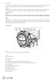
/59 | F-R60K Fire Damper with Quick Mount Kit Description Fire dampers represent passive fire protection, designed with the help of compartmentalization to prevent the spread of toxic gases, smoke and fire. The opening and closure of the damper blade can be activated remotely. In case of fire, when the air in the duct exceeds 72 °C, the thermal fuse melts. Melting of the thermal fuse activates the closure of the damper blade automatically. Damper blade is then mechanically locked in closed position.
/59 | F-R60K Fire Resistivity F-R60K fire dampers are CE certified following the Construction Products Regulation according to EN 15650:2010. Tested according to EN 1366-2:2015 and classified according to EN 13501-3 + A1:2009. The fire damper together with its installation form an inseparable part of the fire resistivity rating. F-R60K fire dampers are designed for the installations listed and described in their Handbook.
/59 | F-R60K Fire damper with an activation mechanism with a Belimo spring return actuator (AC/DC 24 V) with an electro-thermal fuse 72°C and auxiliary switches, with a supply and communication unit (SLC powered) BC24-G2 (THC). • BST2 Fire damper with an activation mechanism with a Belimo spring return actuator (AC/DC 24 V) with an electro-thermal fuse 72°C and auxiliary switches, with a Belimo supply and communication unit (AC 230 V) BKN230-24-MOD (Modbus/BACnet).
/59 | F-R60K Technical Parameters Durability Test 10000 cycles, actuator controlled (0 … 90 degrees rotation) – with no change of the required properties 10000 cycles, actuator controlled for modular possibility (45 ... 60 degrees rotation) - with no change of the required properties Testing Pressure Underpressure up to 300 Pa Safe Position Closed. (In case of fire the damper closes via a spring in the actuator ) Airflow Direction Both directions Allowed Air Velocity Damper can still operate at max.
/59 | F-R60K Maintenance Not required. Dry cleaning if demanded by law in the country in which the dampers are installed. Revisions Determined by law in the country in which the fire dampers are installed. Recommended at least every 12 months.
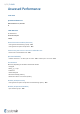
/59 | F-R60K Assessed Performance 21 CE 1396 Systemair Production a.s.
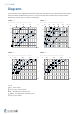
/59 | F-R60K Diagrams The pressure drop and A-weighted total discharged sound power level depend on the nominal diameter of the damper and air flow volume at different duct pressures. The type of activation does not influences the airflow parameter, therefore the activation type is not shown in the diagrams. F-R60K-...-? F-R60K-...
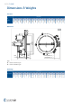
/59 | F-R60K Dimensions & Weights Free Area 140 150 160 180 200 225 250 280 315 355 400 450 500 0,072 0,074 0,076 0,081 0,087 0,094 0,103 0,115 0,130 0,150 0,176 0,208 0,244 560 630 0,356 125 0,292 100 0,069 AV (m2) 0,065 DN (mm) Dimensions 20 DN+80 DN (mm) (45) 100 (45) 190 R1 ≤105 (B230T; B... ) ≤120 (G230T; G... ) Note: B... - Belimo activation types G...
/59 | F-R60K Weights DN (mm) m (kg) 100 125 140 150 160 180 200 225 250 280 315 355 B230T 4,7 4,9 5,3 5,3 5,3 5,7 6,0 6,5 7,0 7,6 8,7 10,1 12,2 14,9 16,5 19,5 22,6 G230T 4,8 5,0 5,4 5,4 5,4 5,8 6,1 6,6 7,1 7,7 8,8 10,2 12,3 15,0 16,6 19,6 22,7 BST0 5,3 5,5 5,9 5,9 5,9 6,3 6,6 7,1 7,6 8,2 9,3 10,7 12,8 15,5 17,1 20,1 23,2 GST0 5,3 5,5 5,9 5,9 5,9 6,3 6,6 7,1 7,6 8,2 9,3 10,7 12,8 15,5 17,1 20,1 23,2 B24T, B24T-W, B24T-SR 4,7 4,9 5,3 5,3
/59 | F-R60K Ordering Code DN Dimension, øDN: 100, 125, 140, 150, 160, 180, 200, 225, 250, 280, 315, 355, 400, 450, 500, 560, 630 mm A - Type of Activation B230T - 230V AC Belimo Actuator G230T - 230V AC Gruner Actuator B24T - 24V AC/DC Belimo Actuator G24T - 24V AC/DC Gruner Actuator B24T-W - 24V AC/DC Belimo Actuator & Wire connector for communication unit G24T-W - 24V AC/DC Gruner Actuator & Wire connector for communication unit B24T-SR - 24V AC/DC Belimo Actuator, modulated 0 V ...
/59 | F-R60K Installation Methods a) b) ≥ 100 mm EI 60 (ve - i ↔ o) S ≥ 100 mm 360° d) F-R60K DN100 ... DN630 ON ≥ 80 mm c) EI 60 (ho - i ↔ o) S ≥ 100 mm ≥ 620 kg/m3 a) F-R60K DN100 ...
/59 | F-R60K • The gap in the installation opening between the damper and the wall/ceiling can be increased by up to 50% of the gap area or decreased to the smallest amount possible that still provides sufficient space for the installation of the seal. • The damper must be earthed after being installed into the duct. • Lists of all permitted installation methods are provided in Handbook.
/59 | F-R60K Installation ON a Wall Standard Flexible & Rigid Wall IMPORTANT: The insulation ring cannot be delivered separately! The insulation ring is delivered pre-mounted on a damper. 1. The supporting construction opening must be prepared as depicted in wall preparation. Opening surfaces must be even and cleaned off. 2. The opening dimension D1 is driven by the nominal dimensions of the damper with added clearance.
/59 | F-R60K 4 2 Y 1 3 (mm) Y1 1 F2 F1 2 ≥50 ≥12,5 DN DN+80 ≥100 D1 ≤ (DN+10) 100 (mm) Y2 1 F2 F1 2 DN DN+80 ≥100 D1 ≤ (DN+10) 100
/59 | F-R60K Opening and Wall and/or Ceiling Preparations 3 4a D1≥600 mm 4c C B 4b A ≥100 mm B 1 øD 1 4c 4d øD 4d D1 2 ≤6 A m 5m C 4a ≥1 00 4a: ≥12,5 mm; ≥1 0 0m mm 4c: ≥50 mm; 4d: ≥50 mm, ≥40 kg/m3 ≥75 ≥200 ≥200 ≥75 Damper Minimum Distances (mm) m
/59 | F-R60K Legend for Installation ON a wall F1 - Screw d=4; e.g. DIN7981 F2 - Fire resistive coating, Kleber K84/Promat or Grena-klebepaste/Grena 1 - Fire damper (F-R60K) 2 - Bendable hanger (part of the sheet metal ring cover) 3 - Concrete/masonry/cellular concrete wall or ceiling 4 - Flexible (plasterboard) wall 4a - 2 layers of plasterboard fireproof plate type F, EN 520 4b - Vertical CW – profiles 4c - Horizontal CW – profiles 4d - Mineral wool; thickness/cubic density see picture.
/59 | F-R60K Installation ON a Shaft Wall One Side Gypsum Covered Wall - 2 Layers IMPORTANT: The insulation ring cannot be delivered separately! The insulation ring is delivered pre-mounted on a damper. 1. The supporting construction opening must be prepared as depicted in wall preparation. Opening surfaces must be even and cleaned off. 2. The opening dimension D1 is driven by the nominal dimensions of the damper with added clearance.
/59 | F-R60K 4 2 Y 1 Y1 1 F2 F1 2 ≥80 (mm) ≥15 D1 ≤ (DN+10) DN DN+80 100
/59 | F-R60K Opening and Wall and/or Ceiling Preparations A 25 ≤6 4a mm C 4c B A 4b D1 øD 1 4c B ≥80 mm C 4a ≥8 0 4a: ≥15 mm; mm 4c: ≥50 mm ≥75 ≥200 ≥200 ≥75 Damper Minimum Distances (mm)
/59 | F-R60K Legend for Installation ON a Shaft Wall F1 - Screw d=4; e.g.
/59 | F-R60K Installation ON a Ceiling Rigid Ceiling, Floor IMPORTANT: The insulation ring cannot be delivered separately! The insulation ring is delivered pre-mounted on a damper. 1. The supporting construction opening must be prepared as depicted in wall preparation. Opening surfaces must be even and cleaned off. 2. The opening dimension D1 is driven by the nominal dimensions of the damper with added clearance. 3.
/59 | F-R60K F3 (mm) Y1 DN+80 1 Y2 Y 2 3 (mm) D1 = DN+40 F12 F11 ≥100 F3 F1 F4 2 F2 ≥100 F2 F4 F10 F3 2 F1 1 100 1 100 DN DN F10 F11 F12 D1 = DN+40 DN+80
/59 | F-R60K Opening and Wall and/or Ceiling Preparations ≥100 mm 3 øD1 ≥75 ≥200 ≥200 ≥75 Damper Minimum Distances (mm)
/59 | F-R60K Legend for Installation ON a Ceiling F1 - Screw d=4; e.g. DIN7981 F2 - Fire resistive coating, Kleber K84/Promat or Grena-klebepaste/Grena F3 - Mineral wool filling (min. 100 kg/m^3) F4 - Fire resistive coating (Hilti CSF-CT). F10 - L shaped hanger, (Hilti MVA-LC; DN100 < 2x ≤ DN250; DN250 < 3x ≤ DN355; DN355 < 4x ≤ DN630) F11 - Screw M8 with suitable wall plug.
/59 | F-R60K Installation OUT of the Wall Standard Flexible & Rigid Wall IMPORTANT: The insulation ring cannot be delivered separately! The insulation ring is delivered pre-mounted on a damper. 1. The supporting construction opening must be prepared as depicted in wall preparation. Opening surfaces must be even and cleaned off. 2. The opening dimension D1 is driven by the nominal dimensions of the damper with added clearance.
/59 | F-R60K A1 F8 F5 2 4 Y 1 LE F7 F9 3 (mm) Y1 F9 F8 F6 1 A1 F1 F5 F2 ≥20 F7 ≥50 ≥12,5 100 D1 ≤ (DN+10) DN DN+80 ≥100 (mm) Y2 F9 F8 F6 1 A1 F1 F5 F2 ≥20 F7 100 D1 ≤ (DN+10) DN DN+80 ≥100
/59 | F-R60K LE > 1000 LE ≤ 1000 Duct Hanger Rules LE ≤ 1000 ≈125 ≤1100 ≈125 ≤1100 ≤1100 LE > 1000 (mm) (mm) Opening and Wall and/or Ceiling Preparations 3 4a D1≥600 mm 4c C B 4b A ≥100 mm B 1 øD 1 4c 4d øD 4d D1 2 ≤6 A m 5m C 4a ≥1 00 4a: ≥12,5 mm; ≥1 0 0m mm 4c: ≥50 mm; 4d: ≥50 mm, ≥40 kg/m3 ≥75 ≥200 ≥200 ≥75 Damper Minimum Distances (mm) m
/59 | F-R60K Legend for Installation OUT of the Standard Wall F1 - Screw d=4; e.g. DIN7981 F2 - Fire resistive coating, Kleber K84/Promat or Grena-klebepaste/Grena F3 - Mineral wool filling (min. 100 kg/m^3) F5 - L-profile 25x25x3 or part of accessory R1-F-R60K ringlet F6 - Self taping screws d=4.2 F7 - M10 Steel threaded rod + M10 nuts (2x on each rod) F8 - Stone wool PAROC Pro Wired Mat 80 AL1 (PAROC), thickness 70 mm, nominal density 80 kg/m^3; Binding wires or wire clamps.
/59 | F-R60K Installation OUT of the Shaft Wall One Side Gypsum Covered Wall - 2 Layers 1. The supporting construction opening must be prepared as depicted in wall preparation. Opening surfaces must be even and cleaned off. 2. The opening dimension D1 is driven by the nominal dimensions of the damper with added clearance. The flexible wall opening must be reinforced as per the shaft plasterboard walls manufacturer instructions (usually only top and bottom horizontal metal beam). 3.
/59 | F-R60K A1 F8 F5 2 4 Y 1 LE F7 F9 Y1 F9 F8 F6 1 A1 F1 F5 F2 ≥80 (mm) ≥15 ≥20 F7 D1 ≤ (DN+10) DN DN+80 100
/59 | F-R60K LE > 1000 LE ≤ 1000 Duct Hanger Rules LE ≤ 1000 ≈125 ≤1100 ≤1100 ≈125 (mm) (mm) Opening and Wall and/or Ceiling Preparations A 4a m 5m 2 ≤6 C 4c B A 4b D1 øD 1 4c B ≥80 mm C 4a ≥8 0 4a: ≥15 mm; mm 4c: ≥50 mm ≥200 ≥200 ≥75 Damper Minimum Distances ≥75 ≤1100 LE > 1000 (mm)
/59 | F-R60K Legend for Installation OUT of the Shaft Wall F1 - Screw d=4; e.g. DIN7981 F2 - Fire resistive coating, Kleber K84/Promat or Grena-klebepaste/Grena F3 - Mineral wool filling (min. 100 kg/m^3) F5 - L-profile 25x25x3 or part of accessory R1-F-R60K ringlet F6 - Self taping screws d=4.2 F7 - M10 Steel threaded rod + M10 nuts (2x on each rod) F8 - Stone wool PAROC Pro Wired Mat 80 AL1 (PAROC), thickness 70 mm, nominal density 80 kg/m^3; Binding wires or wire clamps.
/59 | F-R60K Electrical Connections IMPORTANT • Danger of electric shock! • Switch off the power supply before working on any electrical equipment. • Only qualified electricians are allowed to work on the electrical system. Actuator Size Map DN (mm) A 100 125 140 150 160 180 200 225 250 280 Belimo BFL…-T-... / Gruner 340TA-…-05 315 355 400 450 500 560 Belimo BFN…-T-...
/59 | F-R60K WS - Wire sizing consumption Note Type of Activation B230T IMPORTANT: Risk of electric shock! Switch off the power supply before working on any electrical equipment. Only qualified electricians are allowed to work on the electrical system. Actuator power supply: 230V AC, 50/60 Hz Notes: • A device that disconnects the pole conductors (minimum contact gap 3 mm) is required for isolation from the power supply. • Parallel connection of several actuators possible.
/59 | F-R60K Type of Activation G230T IMPORTANT: Risk of electric shock! Switch off the power supply before working on any electrical equipment. Only qualified electricians are allowed to work on the electrical system. Actuator power supply: 230V AC, 50/60 Hz Notes: • A device that disconnects the pole conductors (minimum contact gap 3 mm) is required for isolation from the power supply. • Parallel connection of several actuators possible.
/59 | F-R60K Type of Activation B24T IMPORTANT: Risk of electric shock! Switch off the power supply before working on any electrical equipment. Only qualified electricians are allowed to work on the electrical system.
/59 | F-R60K Type of Activation G24T IMPORTANT: Risk of electric shock! Switch off the power supply before working on any electrical equipment. Only qualified electricians are allowed to work on the electrical system. Actuator power supply: AC (50/60 Hz)/DC 24 V Notes: • Supply via safety isolation transformer. • Parallel connection of several actuators possible.
/59 | F-R60K Type of Activation B24T-W IMPORTANT: Risk of electric shock! Switch off the power supply before working on any electrical equipment. Only qualified electricians are allowed to work on the electrical system. This type of activation is with provided cable connectors for the supply and communication unit (communication unit not part of the mechanism). Actuator power supply: AC (50/60 Hz)/DC 24 V Notes: • Supply via safety isolation transformer.
/59 | F-R60K Type of Activation G24T-W IMPORTANT: Risk of electric shock! Switch off the power supply before working on any electrical equipment. Only qualified electricians are allowed to work on the electrical system. This type of activation is with provided cable connectors for the supply and communication unit (communication unit not part of the mechanism). Notes: • Supply via safety isolation transformer. • Parallel connection of several actuators possible.
/59 | F-R60K Type of Activation B24T-SR IMPORTANT: Risk of electric shock! Switch off the power supply before working on any electrical equipment. Only qualified electricians are allowed to work on the electrical system. Actuator power supply: AC (50/60 Hz)/DC 24 V Notes: • Supply via safety isolation transformer.
/59 | F-R60K Type of Activation G24T-SR IMPORTANT: Risk of electric shock! Switch off the power supply before working on any electrical equipment. Only qualified electricians are allowed to work on the electrical system. Actuator power supply: AC (50/60 Hz)/DC 24 V Notes: • Supply via safety isolation transformer.
/59 | F-R60K LEDs status indication (BST0) LED colour| LED state | Status Yellow | ON | Damper open Yellow | Blinks | Damper is opening Green | ON | Damper closed Green | Blinks | Damper is closing Yellow or green | Blinks at double frequency | Error Yellow and green | OFF | Power failure 1 BKN230-24 5 4 AC 24 V MOTOR 2 3 1 2 3 4 5 6 7 Notes: • Caution! Main power supply voltage! • Parallel connection of several actuators possible.
/59 | F-R60K • 3 – 4 Use Jumper only for commissioning purposes and without BKS24-..
/59 | F-R60K Type of Activation GST0 • The actuator and the control module are factory wired. • Individual control of 2 fire dampers • Bus protocols (RS-485): BACnet MS/TP and Modbus RTU • Automatic baud rate detection with BACnet • Bus monitoring function LEDs status indication (GST0) LED color and type | LED state | Status Yellow (Closed) | ON | Damper closed Green (Open) | ON | Damper open Yellow and green | Blinks in parallel | Damper is moving Yellow and green | Alternately blinks - interval 0.
/59 | F-R60K IMPORTANT: If only one actuator is connected to the FSC-UFC24-2 the LEDs of the side where no actuator is connected indicate an alarm. A jumper has to be installed between S4 and S6 in the terminal where there is no actuator connected, to indicate an “opened” position in the LED. If the second connection is not activated via bus, there will be no alarm signal on the bus system.
/59 | F-R60K Type of activation BST1 IMPORTANT: Danger of electric shock! Parallel circuits, i.e. a smoke detector on multiple slave devices are not allowed! Switch off the power supply before working on any electrical equipment. Allow only qualified electricians to work on the electrical system. Actuator power supply via fitted communication unit: DC 24 V NOTES: • Left: Connection scheme for fitted communication and supply unit BC24-G2 (THC).
/59 | F-R60K T - Test button: This allows the simple function test on site of the damper. The button operation causes an error message at the control device which must be reset. X2 - 2-pin spring terminal: 1/2 - connection for SLC two-wire line, wires interchangeable. Maximum cable lengths can be calculated with the SLC Planning Tool. Rule of thumb: 300m@1.5 mm2 X3 - 3-pin connector: damper actuator (DC 24 V) X4 - 4-pin spring terminal: Connection for smoke detector • 1- (+) DC 24 V / max.
/59 | F-R60K Type of activation BST2 IMPORTANT: Danger of electric shock! Switch off the power supply before working on any electrical equipment. Allow only qualified electricians to work on the electrical system. Actuator power supply via fitted communication unit: DC 24 V NOTES: • Depiction of parts for fitted communication and supply unit BKN230-24-MOD (Modbus/BACnet).
/59 | F-R60K 1 4 BKN230-24-MOD U 6 2 7 3 1 2 3 4 5 6 7 5 COM ON OFF ON WE Baud A1 Parity Term Bus 1 2 3 4 5 6 1 2 9’600 OFF OFF 19’200 OFF ON 38’400 ON OFF 76’800 ON ON ON T WE 1 2 3 4 5 6 7 8 MSB LSB Address A2 1-8-N-1 3 4 OFF OFF A3 5 A4 6 150 Ω ON BACnet ON OFF OFF Modbus OFF B 1 2 3 4 5 6 7 8 0 - OFF OFF OFF OFF OFF OFF OFF 1 - OFF OFF OFF OFF OFF OFF ON 2 - OFF OFF OFF OFF OFF ON OFF ...
/59 | F-R60K • 2External smoke detector, control input • 3 GND • 4 BKN Direct Control, override control input • 5 Modbus GND • 6 Modbus D+ • 7 Modbus D– 5 - Parametrization: DIL switch • A1:Baud rate • A2:Parity • A3: Termination (on with 150 Ω) • A4: Bus: BACnet (ON) or Modbus (OFF) • B:Modbus address
/59 | F-R60K Type of activation BST3 IMPORTANT: Danger of electric shock! Switch off the power supply before working on any electrical equipment. Allow only qualified electricians to work on the electrical system. Actuator power supply via fitted communication unit: DC 24 V NOTES: • Depiction of parts for fitted communication and supply unit BKN230-24-C-MP (SBS/MP). • The unit can communicate either with the BKS24...-1B, ...
/59 | F-R60K 1 BKN230-24-C-MP 4 5 2 3 1 2 3 4 5 6 7 T Legend T - Button for test and address. 1 - Power supply: cable and plug, AC 230 V 2 - 3-pin connector: damper actuator (DC 24 V) 3 - 6-pin connector: damper actuator (position limit switches) 4 - 2-pin connector: BAT… thermoelectric tripping device 5 - Connecting terminals: • 1External smoke detector, +24 V, max.
/59 | F-R60K Type of activation BST10 IMPORTANT: Danger of electric shock! The BKN230-24-PL may only be used with a designated master (e.g. BKS64-PL). Switch off the power supply before working on any electrical equipment. Allow only qualified electricians to work on the electrical system.
/59 | F-R60K X300 - 4-pin connector: connection for belimo top-line actuator (not used)
/59 | F-R60K Handling & Manipulation Handling and manipulation must be done with care. For safety reasons manipulate the damper in its closed possition and with gloves. Operation Manual Warning: Damper blades are spring loaded in the open position and are closing very quick. To avoid injury, make sure to keep the blade movement area clear while manipulating with the fire damper. After installation, it is necessary to adjust the damper into its operating position – open the fire damper.
/59 | F-R60K Damper Inspection The activation mechanism keeps the dampers on stand-by during their entire life cycle in accordance with this manual issued by the manufacturer. It is not permitted to alter the dampers in any way nor perform any changes to their structure without the manufacturer’s consent. The operator performs regular checks of the dampers as per established regulations and standards at least once every 12 months.
Systemair DESIGN • 2022-07-11 • Handbook_F_R60K_en-GB • Original instructions