
DataSheet CAP CT201811


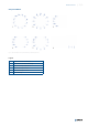
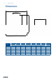
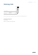
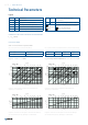
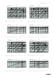
Table Of Contents

6 / 9 | Nozzle Diffusers
Technical Parameters
p
s
Pa Pressure drop
q
V
m
3
/h, l/s Air ow volume
L
WA
dB(A) A-weighted total sound power level
L
W
dB Non-weighted total sound power level
ΔT K Temperature difference Supply air - Room air
L
0,2
m Air throw length with terminal velocity 0,2 m/s
Calculation of Air Throw for Different Terminal Velocities
L
x
= L
0,2
× 0,2/x
Diagram 1: Pressure drop & A-weighted total sound power level
depending on air ow volume
Legend
200
160
120
90
70
60
50
25
30
20 30 35
24060 140
15 2510
40 50 70 120
CAP-CT-100
15
q
V
(m
3
/h)
q
V
(l/s)
p
s
(Pa)
L
WA
= 40 dB(A)
25
80 100 180
20
30
40
30
35
45
40 6050
25% 50% 75%
100%
0%
Diagram 2: Isothermal air throw lengths for horizontal radial discharge
with terminal velocity 0,2 m/s, depending on air ow volume
Diagram 3: Pressure drop & A-weighted total sound power level
depending on air ow volume
Diagram 4: Isothermal air throw lengths for horizontal radial discharge
with terminal velocity 0,2 m/s, depending on air ow volume
180
150
120
90
70
60
50
45
20 30 35
35080 200
25 9015
60
70 90 160
CAP-CT-125
15
q
V
(m
3
/h)
q
V
(l/s)
p
s
(Pa)
L
WA
= 40 dB(A)
25
120 140 250
40
30
35
45
40 45
25%
50% 75%
0%
100%
50 60 70 80
300
3
2
1
0,8
0,6
0,4
30
20 30 35
24060 140
15 2510
40 50 70 120
CAP-CT-100
0,2
q
V
(m
3
/h)
q
V
(l/s)
L
0,2
(m)
80 100 180
40 6050
ΔT = -10 K ΔT = 10 K
0,75 0,83
Correction Tables
NOTE: For vertical distribution see Systemair DESIGN.
e.g.: L
(ΔT = 10 K)
= L
(ΔT = 0 K)
× 0,83
Tab. 2: Correction factors for horizontal distribution Tab. 3: Correction factors for horizontal distribution - alternative nozzle settings
e.g. for 3 way horizontal diffusion: L
0,2 (3 way)
= L
0,2 (radial)
× 1,9
4 way 3 way 2 way 1 way
1,40 1,90 2,30 3,30
3
2
1
0,5
0,3
L
0,2
(m)
20 30 3525 9015
CAP-CT-125
q
V
(l/s)
40 45 50 60 70 80
45 35080 200
60
70 90 160
q
V
(m
3
/h)
120 140 250
300
L
x
m
Air throw length calculated for specic
terminal velocity
x m/s Terminal velocity in range of 0,1 m/s ... 1 m/s
0%,
25%, 50%, 75%,
100%
The plenum box damper positions in pressure drop/
noise diagrams are represented as a percentage.
0% is a fully closed damper.
100% is a fully open damper.