
MODBUS LITE V5.01 parameter specification
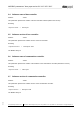

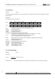
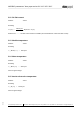
Table Of Contents
- 1 Frame protocol
- 2 Holding Register
- 2.1 Overview
- 2.2 Reset
- 2.3 Default set value
- 2.4 Password
- 2.5 Control default setting
- 2.6 Control customer setting
- 2.7 Operating hours counter
- 2.8 Operating minutes counter
- 2.9 Fan address
- 2.10 Source set value
- 2.11 Preferred running direction
- 2.12 Save set value
- 2.13 Internal parameter set
- 2.14 Control mode
- 2.15 Control parameters
- 2.16 Maximum modulation level
- 2.17 Minimum modulation level
- 2.18 Enable motor stop
- 2.19 Set value (EEPROM)
- 2.20 Starting modulation level
- 2.21 Maximum permissible modulation level
- 2.22 Minimum permissible modulation level
- 2.23 Maximum speed
- 2.24 Maximum permissible speed
- 2.25 Ramp-up curve / ramp-down curve
- 2.26 Limit speed
- 2.27 Potentiometer characteristic
- 2.28 Control limitation
- 2.29 Maximum power
- 2.30 Maximum coil current
- 2.31 Limiting speed for running monitor
- 2.32 Interface settings
- 2.33 Shedding function
- 2.34 Relay dropout delay
- 2.35 Fail safe function on/off
- 2.36 Fail safe function set value
- 2.37 Fail safe function time lag
- 2.38 Fail safe function running direction
- 2.39 Potentiometer characteristic limiting value for cable break
- 2.40 Sensor
- 2.41 Customer data
- 2.42 Error history
- 2.43 Reference value of DC-link voltage
- 2.44 Reference value of DC-link current
- 2.45 Production data
- 3 Input Register
- 3.1 Overview
- 3.2 Identification
- 3.3 Maximum number of bytes
- 3.4 Software name of bus controller
- 3.5 Software version of bus controller
- 3.6 Software name of commutation controller
- 3.7 Software version of commutation controller
- 3.8 Actual speed
- 3.9 Motor status
- 3.10 Warning
- 3.11 DC-link voltage
- 3.12 DC-link current
- 3.13 Module temperature
- 3.14 Motor temperature
- 3.15 Interior electronics temperature
- 3.16 Current direction of rotation
- 3.17 Current modulation level
- 3.18 Current set value
- 3.19 Sensor actual values
- 3.20 Current parameter set
- 3.21 Current power

MODBUS parameters "ebm-papst series 84 / 112 / 150 / 200"
_______________________________________________________________________________________
ebm-papst Mulfingen GmbH & Co. KG
Bachmühle 2 ·74673 Mulfingen, Germany ·Phone: +49 (0) 7938/81-0 ·Fax: +49 (0) 7938/81-110 ·www.ebmpapst.com ·info1@de.ebmpapst.com
DocNo.: 634505DocNo.: 446144DocNo.:358982DocNo.:322523DocNo.:309753DocNo.:303997DocNo.:276241DocNo.:256078DocNo.:196392 ·Template: 2 dated 6 October 2003 ·File: ext001157859.doc ·Last printed 10/03/2015 15:13:00
·Page 63 of 70
Form 1003
3.2 Identification
Address : D000
Identification specifies the type of electronics and protocol concerned.
Encoding:
Value
Device
Specification version
00 01
ebm-papst series 84 / 112 / 150
1.02
*)
00 02
ebm-papst series 84 / 112 / 150
2.01, 3.00 - 3.01
*)
00 03
Customer application
*)
00 04
Customer application
*)
00 05
Customer application
*)
00 06
ebm-papst series 84 / 112 / 150
3.02
*)
00 07
ebm-papst series 84 / 112 / 150
4.00
*)
00 08
ebm-papst series 84 / 112 / 150 / 200
5.00
*)
00 09
Customer application
*)
00 0A
ebm-papst series 84 / 112 / 150 / 200 Lite
5.00 Lite
*)
00 0B
ebm-papst series 84 / 112 / 150 / 200 Lite + addon module
5.00
*)
00 0C
Special applications for ebm-papst series 84 / 112 / 150 / 200
5.02
*)
00 0D
ebm-papst series 84 / 112 / 150 / 200 Lite
5.01 Lite
04 00
Customer application
*)
05 00
Customer application
*)
06 00
Customer application
*)
07 00
Customer application
*)
08 00
Customer application
*)
*)
Devices with identification ≠ 0x000D do not correspond to this specification.
In such cases, the corresponding document should be used.
3.3 Maximum number of bytes
Address : D001
This parameter specifies the maximum number of bytes that a telegram sent via MODBUS may contain.
Encoding:
bytes Databytes of number Max.