
MODBUS LITE V5.01 parameter specification
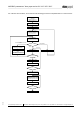

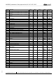

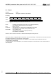
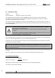
Table Of Contents
- 1 Frame protocol
- 2 Holding Register
- 2.1 Overview
- 2.2 Reset
- 2.3 Default set value
- 2.4 Password
- 2.5 Control default setting
- 2.6 Control customer setting
- 2.7 Operating hours counter
- 2.8 Operating minutes counter
- 2.9 Fan address
- 2.10 Source set value
- 2.11 Preferred running direction
- 2.12 Save set value
- 2.13 Internal parameter set
- 2.14 Control mode
- 2.15 Control parameters
- 2.16 Maximum modulation level
- 2.17 Minimum modulation level
- 2.18 Enable motor stop
- 2.19 Set value (EEPROM)
- 2.20 Starting modulation level
- 2.21 Maximum permissible modulation level
- 2.22 Minimum permissible modulation level
- 2.23 Maximum speed
- 2.24 Maximum permissible speed
- 2.25 Ramp-up curve / ramp-down curve
- 2.26 Limit speed
- 2.27 Potentiometer characteristic
- 2.28 Control limitation
- 2.29 Maximum power
- 2.30 Maximum coil current
- 2.31 Limiting speed for running monitor
- 2.32 Interface settings
- 2.33 Shedding function
- 2.34 Relay dropout delay
- 2.35 Fail safe function on/off
- 2.36 Fail safe function set value
- 2.37 Fail safe function time lag
- 2.38 Fail safe function running direction
- 2.39 Potentiometer characteristic limiting value for cable break
- 2.40 Sensor
- 2.41 Customer data
- 2.42 Error history
- 2.43 Reference value of DC-link voltage
- 2.44 Reference value of DC-link current
- 2.45 Production data
- 3 Input Register
- 3.1 Overview
- 3.2 Identification
- 3.3 Maximum number of bytes
- 3.4 Software name of bus controller
- 3.5 Software version of bus controller
- 3.6 Software name of commutation controller
- 3.7 Software version of commutation controller
- 3.8 Actual speed
- 3.9 Motor status
- 3.10 Warning
- 3.11 DC-link voltage
- 3.12 DC-link current
- 3.13 Module temperature
- 3.14 Motor temperature
- 3.15 Interior electronics temperature
- 3.16 Current direction of rotation
- 3.17 Current modulation level
- 3.18 Current set value
- 3.19 Sensor actual values
- 3.20 Current parameter set
- 3.21 Current power

MODBUS parameters "ebm-papst series 84 / 112 / 150 / 200"
_______________________________________________________________________________________
ebm-papst Mulfingen GmbH & Co. KG
Bachmühle 2 ·74673 Mulfingen, Germany ·Phone: +49 (0) 7938/81-0 ·Fax: +49 (0) 7938/81-110 ·www.ebmpapst.com ·info1@de.ebmpapst.com
DocNo.: 634505DocNo.: 446144DocNo.:358982DocNo.:322523DocNo.:309753DocNo.:303997DocNo.:276241DocNo.:256078DocNo.:196392 ·Template: 2 dated 6 October 2003 ·File: ext001157859.doc ·Last printed 10/03/2015 15:13:00
·Page 28 of 70
Form 1003
2.2 Reset
Address : D000
Write authorisation : ebm-papst, customer, end customer
Encoding:
MSB
0
0
0
0
0
0
0
0
LSB
0
0
0
0
Reset
Error
Parameter
AWS Rst
A bit will trigger the following action in the fan when it is set:
Reset : Software reset (includes "Reset error" and "Adopt parameters")
The software is launched at the start of booting
Error : Errors are reset
Parameter : All parameters are copied from the EEPROM into the RAM
This bit must be set to make revised parameters valid
Reset AWS : User software reset
(includes "Reset error" and "Adopt parameters")
The software is reinitialised
After the action has been executed, the bit will automatically be reset by the fan.
When reset (bit 3), the program will be relaunched at the start of booting. Commands from the master will then
be neither responded to nor executed for a few seconds.
Reset (bit 3) is only recommended if new user software is to be loaded using a bootloader (because
communication is interrupted).
If only the software is to be reinitialised, user software reset (bit 0) is recommended. Then communication is
not interrupted.