
SYSTEMP Engineering Data Manual (EDM SYSTEMP S 7GB)


Specications
|
55
For the units with monobloc structure the drain tray is
made by galvanized steel of 1mm-thickness painted in an-
thracite colour RAL 7024.
Valid for models:
ST OPA/UPA 071-141-211-251-321-322
ST OPU/UPU 10-20-30-50
ST HRA 121-201-231-361
ST HRU 20-40.
Electrical panel
The machines are equipped with a complete electrical con-
trol panel with:
A yellow/red main switch with door-locking function on
the outside of the panel
Protection of utilities against short-circuits and overload-
ing (valid also as a standard for condensing temperature
exceeding 55°C)
Single-phase isolation transformer to power the auxiliary
circuit at 24 Volt AC.
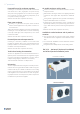
Microprocessor control system and user display
The user terminal is tted with a large colour display (320 x
240 pixels) and touch keys to view information on the units'
control software. A remote control terminal is available.
A microprocessor-based control system with LED numerical
display forecasts observation of the following values:
Temperature set-point (read and write)
Suction Temperature (read)
Supply Temperature (read)
Humidity set-point (read and write)
Suction humidity (accessory)
Supply humidity (accessory)
Date and time.
The operating modes are shown on the display panel with
dedicated icons.
Alarm condition are signalled with an audible and visual
alarm.
The keyboard LEDS will indicate active alarm, power supply
presence and unit conditions.
Alarms log
Unit memory records 100 recent alarms with time and date
stamp for each alarm with LI-FO logic management.
Alarm monitor
The control system monitors unit operation and activate an
audible and visual alarm in the event either of the follow-
ing factories present alarm conditions occurs:
High / Low temperature
High / Low humidity
Clogged lter
Fan/s alarm
Humidier alarms
Cooling circuits components alarm (for units with chilled
water circuit only)
Water leakage under unit
Power lost
Sensors and probes alarms
Fire/Smoke detection alarm, (customizable Digital Input).
(Terminal Block for connection of an external smoke/re
alarm signal)
Customizable digital outputs/input
Customizable digital outputs
The microprocessor is able to control up to four digital
outputs freely congurable by the user.
It is possible to congure one of the following types of
control for each digital output:
Water pump control
Condensing unit control
Unit status signal
Cooling / heating status signal
Humidication / dehumidication status signal
Free cooling status signal
General alarm signal
Non-critical alarm signal
Critical alarm signal
Dirty lters alarm signal
Cooling / heating alarm signal
Fans alarm signal
Temperature alarm signal
Humidity alarm signal
Flooding / condensate drain alarm signal.
Customizable digital input
The microprocessor is able to control up to four digital In-
puts freely congurable by the user.
It is possible to congure one of the following types of con-
trols for each digital input:
Fire/Smoke Alarm
General water pump alarm
External humidier general alarm
General supply fans alarm
Condenser 1 and 2 general alarm
Dry cooler general alarm
Gas leak detector alarm
Condensing unit generic alarm
Non-critical generic alarm
Critical generic alarm
STOP cooling, heating, humidication, dehumidication,
heating & humidication, cooling & heating & humidi-
cation, free cooling
Free cooling override
2nd Source two sources override.