
SYSTEMP Engineering Data Manual (EDM SYSTEMP S 7GB)
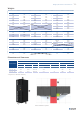

Technical data
|
3535
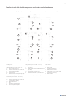
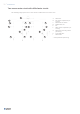
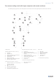
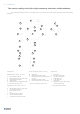
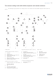
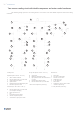
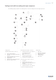
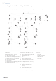
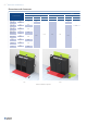
The following image represents the cooling circuit in two sources units with double compressor and remote con-
denser.
Cooling circuit:
Liquid line (HP liq: PS 45 Bar - TS 68 °C):
A Liquid line
B Liquid line cock
C Pressure intake SAE 5/16” male are
D Liquid temperature probe
E Liquid receiver
F Safety valve (44 Bar)
G Dehydrator lter with liquid sight glass
H Electronic expansion valve
Suction line (LP: PS 22 Bar - TS 38 °C):
I Pressure intake SAE 5/16” male are (for
refrigerant charging)
J Direct expansion coil
K Fan
L Evaporation pressure probe
M Suction temperature probe
N Antifreeze hot gas injection valve
Hot gas line (HP gas: PS 41 Bar - TS 64 °C):
O Compressor
P Discharge temperature probe
Q High pressure switch with manual reset
(41 Bar)
R Hot gas line check valve
S Pressure intake SAE 5/16” male are
T Condensation pressure probe
U Hot gas line cock
V Hot gas line
* DC inverter compressor (accessory):
1 DC inverter compressor
2 Oil separator
Water circuit:
a Water inlet
b Inlet water temperature
c Manual air vent valves
d Chilled water coil
e 3-way ball valve
f Water outlet
** 2-way ball valve (accessory)
c
a
f
e
b
c
d
A
S
G
I
E
D
K
J
L
B
H
I
R
M
C
Q
O
P
T
U
V
1
2
N
F
A
S
G
I
E
D
L
B
H
I
R
M
C
Q
O
P
T
U
V
N
F
Two sources cooling circuit with double compressor and remote condenser