
SYSTEMP Engineering Data Manual (EDM SYSTEMP S 7GB)

Technical data
|
2727
Chilled water circuit
TMC air-cooled condenser cooling circuit
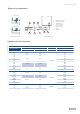
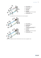
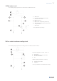
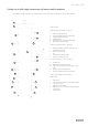
The following image represents the cooling circuit of a TMC air-cooled condenser.
A Water inlet
B Inlet water temperature (accessory)
C Manual air vent valves
D Chilled water coil
E Fan
F Outlet water temperature (accessory)
G Water ow measuring device (accessory)
H 3-way ball valve
I Water outlet
* 2-way ball valve (accessory)
C
F
A
G
E
D
B
C
H
I
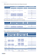
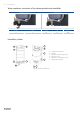
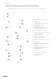
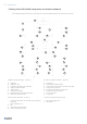
The following image represents the water circuit of chilled water units.
Hot gas line (HP gas: PS 41 Bar - TS 64 °C):
A Hot gas line
B Pressure intake SAE 1/4” male are
C Air-cooled condenser
D Fan
Liquid line (HP liq: PS 45 Bar - TS 68 °C):
E Liquid line check valve
F Liquid line
* LAC (Low Ambient Control) Valve (Accessory)
C
A F
D
B
B
E