
Topvex Softcooler SR Operation and Maintenance 208766A003


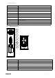

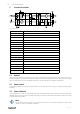
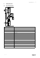
Table Of Contents

4
|
Function Description
5 Function Description
RC
RM
HE
EV
CO
FC
HPS
CPR
EV
CO
FC
HPS
CPR
Fig. 4 Left hand unit
Position Description
EF
Extract air fan
SF
Supply air fan
SS
Temp. sensor supply air
OS
Temp. sensor outdoor air
ETS Temp. sensor extract air
UC
Control unit
RC
Rotor control
RM Rotor motor
HE
Exchanger
DO
Damper outdoor air (accessory)
DEH
Damper exhaust air (accessory)
FC Frequency converter
CPR Compressor
EV Evaporator
CO
Condenser
HPS
Condenser pressure sensor
OT/ET Overheating/Max. temp switches
FGS/FGE Air filter pressure switches
5.1 General
Control unit (UC) senses the temperature via the extract temperature sensor (ETS) and then keep the set extract tem-
perature by sequence controlling the compressor (CPR), heat exchanger (HE) and hot water- /electrical heater (HWL/H,
ELH). The temperature sensor in the supply air (SS) is min. and max. limiting the supply air temperature.
5.2 Power control
The compressor (CPR) are step-less controlled between, in the frequency converter (FC), set minimum and maximum
frequency.
5.3 Power limitation
The programmable controller is continuously sensing the condensing pressure via the high pressure sensor (HPS) and
gradually slows down the speed of the compressor (CPR), if the pressure exceeds the set limitation value. This is done
to avoid a high pressure alarm.
Note:
This instruction contains functions for the Topvex SoftCooler SR, for a complete description of functions see
" SR 09,11, TR 09-15 Installation instruction".
208766 | A003