
MODBUS LITE V5.01 parameter specification


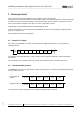
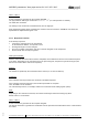
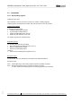
Table Of Contents
- 1 Frame protocol
- 2 Holding Register
- 2.1 Overview
- 2.2 Reset
- 2.3 Default set value
- 2.4 Password
- 2.5 Control default setting
- 2.6 Control customer setting
- 2.7 Operating hours counter
- 2.8 Operating minutes counter
- 2.9 Fan address
- 2.10 Source set value
- 2.11 Preferred running direction
- 2.12 Save set value
- 2.13 Internal parameter set
- 2.14 Control mode
- 2.15 Control parameters
- 2.16 Maximum modulation level
- 2.17 Minimum modulation level
- 2.18 Enable motor stop
- 2.19 Set value (EEPROM)
- 2.20 Starting modulation level
- 2.21 Maximum permissible modulation level
- 2.22 Minimum permissible modulation level
- 2.23 Maximum speed
- 2.24 Maximum permissible speed
- 2.25 Ramp-up curve / ramp-down curve
- 2.26 Limit speed
- 2.27 Potentiometer characteristic
- 2.28 Control limitation
- 2.29 Maximum power
- 2.30 Maximum coil current
- 2.31 Limiting speed for running monitor
- 2.32 Interface settings
- 2.33 Shedding function
- 2.34 Relay dropout delay
- 2.35 Fail safe function on/off
- 2.36 Fail safe function set value
- 2.37 Fail safe function time lag
- 2.38 Fail safe function running direction
- 2.39 Potentiometer characteristic limiting value for cable break
- 2.40 Sensor
- 2.41 Customer data
- 2.42 Error history
- 2.43 Reference value of DC-link voltage
- 2.44 Reference value of DC-link current
- 2.45 Production data
- 3 Input Register
- 3.1 Overview
- 3.2 Identification
- 3.3 Maximum number of bytes
- 3.4 Software name of bus controller
- 3.5 Software version of bus controller
- 3.6 Software name of commutation controller
- 3.7 Software version of commutation controller
- 3.8 Actual speed
- 3.9 Motor status
- 3.10 Warning
- 3.11 DC-link voltage
- 3.12 DC-link current
- 3.13 Module temperature
- 3.14 Motor temperature
- 3.15 Interior electronics temperature
- 3.16 Current direction of rotation
- 3.17 Current modulation level
- 3.18 Current set value
- 3.19 Sensor actual values
- 3.20 Current parameter set
- 3.21 Current power

MODBUS parameters "ebm-papst series 84 / 112 / 150 / 200"
_______________________________________________________________________________________
ebm-papst Mulfingen GmbH & Co. KG
Bachmühle 2 ·74673 Mulfingen, Germany ·Phone: +49 (0) 7938/81-0 ·Fax: +49 (0) 7938/81-110 ·www.ebmpapst.com ·info1@de.ebmpapst.com
DocNo.: 634505DocNo.: 446144DocNo.:358982DocNo.:322523DocNo.:309753DocNo.:303997DocNo.:276241DocNo.:256078DocNo.:196392 ·Template: 2 dated 6 October 2003 ·File: ext001157859.doc ·Last printed 10/03/2015 15:13:00
·Page 6 of 70
Form 1003
1 Frame protocol
Data are transferred using the MODBUS protocol defined in these specifications
exclusively in an environment defined as a master/slave system. The orderly progression of data is defined by
the master. A slave is required to respond to its command prompt. For this reason, it is important to ensure
that no slave address is assigned more than once when constructing a system.
A twisted pair wire with RS485 standard should preferably be used.
Only RTU transmission mode is supported (see MODBUS over Serial Line Specification & Implementation
guide V1.0, chapter 2.5.1)
ASCII transmission mode is not supported!
1.1 Structure of a byte
According to the MODBUS over Serial Line Specification & Implementation guide V1.0. a byte has the
following structure:
Start
(low)
Bit 0
(LSB)
Bit 1
Bit 2
Bit 3
Bit 4
Bit 5
Bit 6
Bit 7
(MSB)
Parity
Stop
(high)
The definition of the parity bit ("Even", "Odd", "None") can be set with the parameter "Parity configuration"
(see 2.32.2).
The transmission rate is variable and can be set with the "transmission rate" parameter (see 2.32.1).
1.2 Communication process
The MODBUS over Serial Line Specification & Implementation guide V1.0 defines the following framework for
the transmission protocol:
Command from
master:
Response from fan:
Address
8 bits
Command
8 bits
Data
N * 8 bits
CRC H
8 bits
CRC L
8 bits
Start
> 3.5 char
Address
8 bits
Command
8 bits
Data
N * 8 bits
CRC H
8 bits
CRC L
8 bits
Start
> 3.5 char
In contrast to the general specifications, the maximum telegram length is 23 bytes!