
MODBUS LITE V5.01 parameter specification
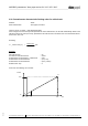

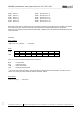

Table Of Contents
- 1 Frame protocol
- 2 Holding Register
- 2.1 Overview
- 2.2 Reset
- 2.3 Default set value
- 2.4 Password
- 2.5 Control default setting
- 2.6 Control customer setting
- 2.7 Operating hours counter
- 2.8 Operating minutes counter
- 2.9 Fan address
- 2.10 Source set value
- 2.11 Preferred running direction
- 2.12 Save set value
- 2.13 Internal parameter set
- 2.14 Control mode
- 2.15 Control parameters
- 2.16 Maximum modulation level
- 2.17 Minimum modulation level
- 2.18 Enable motor stop
- 2.19 Set value (EEPROM)
- 2.20 Starting modulation level
- 2.21 Maximum permissible modulation level
- 2.22 Minimum permissible modulation level
- 2.23 Maximum speed
- 2.24 Maximum permissible speed
- 2.25 Ramp-up curve / ramp-down curve
- 2.26 Limit speed
- 2.27 Potentiometer characteristic
- 2.28 Control limitation
- 2.29 Maximum power
- 2.30 Maximum coil current
- 2.31 Limiting speed for running monitor
- 2.32 Interface settings
- 2.33 Shedding function
- 2.34 Relay dropout delay
- 2.35 Fail safe function on/off
- 2.36 Fail safe function set value
- 2.37 Fail safe function time lag
- 2.38 Fail safe function running direction
- 2.39 Potentiometer characteristic limiting value for cable break
- 2.40 Sensor
- 2.41 Customer data
- 2.42 Error history
- 2.43 Reference value of DC-link voltage
- 2.44 Reference value of DC-link current
- 2.45 Production data
- 3 Input Register
- 3.1 Overview
- 3.2 Identification
- 3.3 Maximum number of bytes
- 3.4 Software name of bus controller
- 3.5 Software version of bus controller
- 3.6 Software name of commutation controller
- 3.7 Software version of commutation controller
- 3.8 Actual speed
- 3.9 Motor status
- 3.10 Warning
- 3.11 DC-link voltage
- 3.12 DC-link current
- 3.13 Module temperature
- 3.14 Motor temperature
- 3.15 Interior electronics temperature
- 3.16 Current direction of rotation
- 3.17 Current modulation level
- 3.18 Current set value
- 3.19 Sensor actual values
- 3.20 Current parameter set
- 3.21 Current power

MODBUS parameters "ebm-papst series 84 / 112 / 150 / 200"
_______________________________________________________________________________________
ebm-papst Mulfingen GmbH & Co. KG
Bachmühle 2 ·74673 Mulfingen, Germany ·Phone: +49 (0) 7938/81-0 ·Fax: +49 (0) 7938/81-110 ·www.ebmpapst.com ·info1@de.ebmpapst.com
DocNo.: 634505DocNo.: 446144DocNo.:358982DocNo.:322523DocNo.:309753DocNo.:303997DocNo.:276241DocNo.:256078DocNo.:196392 ·Template: 2 dated 6 October 2003 ·File: ext001157859.doc ·Last printed 10/03/2015 15:13:00
·Page 57 of 70
Form 1003
2.41 Customer data
Address : D170 - D17F
Write authorisation : ebm-papst, customer
For the customer, a total of 16 parameters (each with 16 bits) is available in this range.
Any values can be stored here.
The behaviour of the fan is not influenced by these parameters.
2.42 Error history
Address of error indicator : D182
Address of 1st error: : D184
Address of 1st error time: : D185
Address of error history 1 to 13 : D186, D188, D18A, D18C, D18E, D190, D192, D194, D196, D198,
D19A, D19C, D19E
Address of error history time 1 to 13 : D187, D189, D18B, D18D, D18F, D191, D193, D195, D197, D199,
D19B, D19D, D19F
Write authorisation : ebm-papst
A) 1st error
The first error that is detected in the service life of the fan is stored under the "1st error" parameter.
At the same time, the reading on the operating hour counter at this time is stored in the parameter "1st error
time". The parameters are automatically written to by the fan.
B) Error history
The error history contains the last 13 errors that were detected in the fan.
The record of each error includes the respective operating hours counter reading in the parameter "Error
history timing". The parameters are automatically written to by the fan.
The error indicator (D182) specifies the address of the last error to be detected in the error history.
The previous error is then at the preceding address.
Example:
Error indicator = D196
Then:
D196 Last error (error n) D197 Time of last error (error n)
D194 Error n-1 D195 Time of error n-1
D192 Error n-2 D193 Time of error n-2
D190 Error n-3 D191 Time of error n-3
D18E Error n-4 D18F Time of error n-4
D18C Error n-5 D18D Time of error n-5
D18A Error n-6 D18B Time of error n-6