
MODBUS LITE V5.01 parameter specification
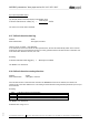
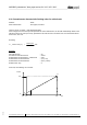


Table Of Contents
- 1 Frame protocol
- 2 Holding Register
- 2.1 Overview
- 2.2 Reset
- 2.3 Default set value
- 2.4 Password
- 2.5 Control default setting
- 2.6 Control customer setting
- 2.7 Operating hours counter
- 2.8 Operating minutes counter
- 2.9 Fan address
- 2.10 Source set value
- 2.11 Preferred running direction
- 2.12 Save set value
- 2.13 Internal parameter set
- 2.14 Control mode
- 2.15 Control parameters
- 2.16 Maximum modulation level
- 2.17 Minimum modulation level
- 2.18 Enable motor stop
- 2.19 Set value (EEPROM)
- 2.20 Starting modulation level
- 2.21 Maximum permissible modulation level
- 2.22 Minimum permissible modulation level
- 2.23 Maximum speed
- 2.24 Maximum permissible speed
- 2.25 Ramp-up curve / ramp-down curve
- 2.26 Limit speed
- 2.27 Potentiometer characteristic
- 2.28 Control limitation
- 2.29 Maximum power
- 2.30 Maximum coil current
- 2.31 Limiting speed for running monitor
- 2.32 Interface settings
- 2.33 Shedding function
- 2.34 Relay dropout delay
- 2.35 Fail safe function on/off
- 2.36 Fail safe function set value
- 2.37 Fail safe function time lag
- 2.38 Fail safe function running direction
- 2.39 Potentiometer characteristic limiting value for cable break
- 2.40 Sensor
- 2.41 Customer data
- 2.42 Error history
- 2.43 Reference value of DC-link voltage
- 2.44 Reference value of DC-link current
- 2.45 Production data
- 3 Input Register
- 3.1 Overview
- 3.2 Identification
- 3.3 Maximum number of bytes
- 3.4 Software name of bus controller
- 3.5 Software version of bus controller
- 3.6 Software name of commutation controller
- 3.7 Software version of commutation controller
- 3.8 Actual speed
- 3.9 Motor status
- 3.10 Warning
- 3.11 DC-link voltage
- 3.12 DC-link current
- 3.13 Module temperature
- 3.14 Motor temperature
- 3.15 Interior electronics temperature
- 3.16 Current direction of rotation
- 3.17 Current modulation level
- 3.18 Current set value
- 3.19 Sensor actual values
- 3.20 Current parameter set
- 3.21 Current power

MODBUS parameters "ebm-papst series 84 / 112 / 150 / 200"
_______________________________________________________________________________________
ebm-papst Mulfingen GmbH & Co. KG
Bachmühle 2 ·74673 Mulfingen, Germany ·Phone: +49 (0) 7938/81-0 ·Fax: +49 (0) 7938/81-110 ·www.ebmpapst.com ·info1@de.ebmpapst.com
DocNo.: 634505DocNo.: 446144DocNo.:358982DocNo.:322523DocNo.:309753DocNo.:303997DocNo.:276241DocNo.:256078DocNo.:196392 ·Template: 2 dated 6 October 2003 ·File: ext001157859.doc ·Last printed 10/03/2015 15:13:00
·Page 56 of 70
Form 1003
2.40 Sensor
Address for min. sensor value : D160 / D161
Address for max. sensor value : D162 / D163
Address of sensor unit : D164 - D169
Write authorisation : ebm-papst, customer, end customer
These values define the characteristic of the specified sensor as shown in the following diagram.
10V
Maximum sensor
value
Minimum sensor
value
0V
U[V]
Rg [unit]
4mA
20mA
The necessary data for min. sensor value and max. sensor value can be found in the data sheet for the
sensor.
These parameters are only intended for use in the master. The behaviour of the fan is not influenced by these
parameters.
Encoding:
a) Minimum sensor value
bytesDataunitphysvaluesensorMin ].[.
The minimum sensor value is stored in "IEEE float" format.
b) Maximum sensor value
bytesDataunitphysvaluesensorMax ].[.
The maximum sensor value is stored in "IEEE float" format.
c) Sensor unit
bytesDataASCIIunitSensor ][
The sensor unit is stored in "ASCII" format.