
MODBUS LITE V5.01 parameter specification
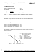
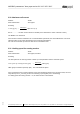
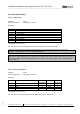
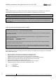
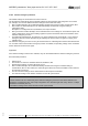
Table Of Contents
- 1 Frame protocol
- 2 Holding Register
- 2.1 Overview
- 2.2 Reset
- 2.3 Default set value
- 2.4 Password
- 2.5 Control default setting
- 2.6 Control customer setting
- 2.7 Operating hours counter
- 2.8 Operating minutes counter
- 2.9 Fan address
- 2.10 Source set value
- 2.11 Preferred running direction
- 2.12 Save set value
- 2.13 Internal parameter set
- 2.14 Control mode
- 2.15 Control parameters
- 2.16 Maximum modulation level
- 2.17 Minimum modulation level
- 2.18 Enable motor stop
- 2.19 Set value (EEPROM)
- 2.20 Starting modulation level
- 2.21 Maximum permissible modulation level
- 2.22 Minimum permissible modulation level
- 2.23 Maximum speed
- 2.24 Maximum permissible speed
- 2.25 Ramp-up curve / ramp-down curve
- 2.26 Limit speed
- 2.27 Potentiometer characteristic
- 2.28 Control limitation
- 2.29 Maximum power
- 2.30 Maximum coil current
- 2.31 Limiting speed for running monitor
- 2.32 Interface settings
- 2.33 Shedding function
- 2.34 Relay dropout delay
- 2.35 Fail safe function on/off
- 2.36 Fail safe function set value
- 2.37 Fail safe function time lag
- 2.38 Fail safe function running direction
- 2.39 Potentiometer characteristic limiting value for cable break
- 2.40 Sensor
- 2.41 Customer data
- 2.42 Error history
- 2.43 Reference value of DC-link voltage
- 2.44 Reference value of DC-link current
- 2.45 Production data
- 3 Input Register
- 3.1 Overview
- 3.2 Identification
- 3.3 Maximum number of bytes
- 3.4 Software name of bus controller
- 3.5 Software version of bus controller
- 3.6 Software name of commutation controller
- 3.7 Software version of commutation controller
- 3.8 Actual speed
- 3.9 Motor status
- 3.10 Warning
- 3.11 DC-link voltage
- 3.12 DC-link current
- 3.13 Module temperature
- 3.14 Motor temperature
- 3.15 Interior electronics temperature
- 3.16 Current direction of rotation
- 3.17 Current modulation level
- 3.18 Current set value
- 3.19 Sensor actual values
- 3.20 Current parameter set
- 3.21 Current power

MODBUS parameters "ebm-papst series 84 / 112 / 150 / 200"
_______________________________________________________________________________________
ebm-papst Mulfingen GmbH & Co. KG
Bachmühle 2 ·74673 Mulfingen, Germany ·Phone: +49 (0) 7938/81-0 ·Fax: +49 (0) 7938/81-110 ·www.ebmpapst.com ·info1@de.ebmpapst.com
DocNo.: 634505DocNo.: 446144DocNo.:358982DocNo.:322523DocNo.:309753DocNo.:303997DocNo.:276241DocNo.:256078DocNo.:196392 ·Template: 2 dated 6 October 2003 ·File: ext001157859.doc ·Last printed 10/03/2015 15:13:00
·Page 48 of 70
Form 1003
2.32 Interface settings
2.32.1 Transfer rate
Address : D149
Write authorisation : ebm-papst, customer
Encoding:
Value
Transfer rate
0x01
2400 bit/sec
0x02
4800 bit/sec
0x03
9600 bit/sec
0x04
19,200 bit/sec
0x05
38,400 bit/sec
0x06
57,600 bit/sec
0x07
115,200 bit/sec
The MSB is of no relevance!
The standard value 19,200 bit/sec (0x04) is recommended for the transmission rate.
Make sure that the same transmission rate is selected for the fan as for the master (e.g. EC Control).
Otherwise, communication with the fan will not be possible!
If the value set by the customer (holding register D249) or the factory default setting (holding register D2C9)
differ from the value selected here, ensure that the transmission rate is also changed after data transfer from
the customer setting or factory default setting (see 2.5 and 2.6). No communication is then possible with the
previous setting
2.32.2 Parity configuration
Address : D14A
Write authorisation : ebm-papst, customer
Encoding:
Value
Parity configuration
Number of
data bits
Parity
Number of
stop bits
0x00
8E1
8
Even
1
0x01
8O1
8
Odd
1
0x02
8N2
8
None
2
0x03
8N1
8
None
1
The MSB is of no relevance!
The standard value 8E1 (0x00) is recommended for the parity configuration.