3825 Ohio Avenue St.
Fire Alarm System Limitations While a fire alarm system may lower insurance rates, it is not a substitute for fire insurance! An automatic fire alarm system–typically made up of smoke detectors, heat detectors, manual pull stations, audible warning devices, and a fire alarm control with remote notification capability–can provide early warning of a developing fire. Such a system, however, does not assure protection against property damage or loss of life resulting from a fire.
Installation Precautions Adherence to the following will aid in problem-free installation with long-term reliability: WARNING - Several different sources of power can be connected to the fire alarm control panel. Disconnect all sources of power before servicing. Control unit and associated equipment may be damaged by removing and/or inserting cards, modules, or interconnecting cables while the unit is energized.
NFPA Standards NFPA Standards This control panel complies with the following NFPA standards: • NFPA 13 - Sprinkler Systems • NFPA 15 - Water Spray Systems • NFPA 16 - Foam-Water Deluge Systems and Foam-Water Spray Systems • NFPA 72 - Central Station Signaling Systems (Automatic, Manual, and Waterflow) - Protected Premises Unit Requires NOTI-FIRE 911AC DACT or 411UDAC Universal Digital Alarm Communicator • NFPA 72 - Local Fire Alarm Systems (Automatic, Manual, Waterflow and Sprinkler Supervisory) • NFPA 72
Table of Contents Table of Contents NFPA Standards.......................................................................................................... 4 NFPA Standards .................................................................................................... 4 Underwriters Laboratories Documents ................................................................. 4 Other....................................................................................................................... 4 1.
Table of Contents Setup and Configuration....................................................................................... 25 Transmitter Module - 4XTM ........................................................................ 25 Zone Relay Module - 4XZM ........................................................................ 26 LED Interface Module - 4XLM .................................................................... 27 Setting Mode of Operation ..................................................
1. Product Description Overview The PDRP-1001 Series Deluge - Preaction Control System has been designed as a control center for use in single- and dual-hazard deluge and preaction applications. The panel is a feature-packed control unit suitable to perform detection and control functions associated with the release of water-based fire protection systems.
1. Product Description Circuits Circuits Input Circuits Initiating Device Circuit #1 (Style B/D) Initiating Device Circuit #2 (Style B/D) Waterflow (Style B/D) Supervisory (Style B/D) Output circuits NAC 1 - Alarm/Waterflow (Style Y/Z) NAC 2 - Waterflow/Supervisory (Style Y/Z) Releasing Circuit 1 (Style Y) Releasing Circuit 2 - Supervisory (Style Y) Note: Zone Relay Module (4XZM) tracks these four circuits.
1.
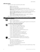
1. Product Description DIP Switch Functions DIP Switch Functions The table below describes the DIP switch functions. For a more detailed explaination see "Setting Mode of Operation" on page 28. #1 & #2 Mode of Operation Determines how NACs and Releasing Circuits respond to an alarm. #3, #4 & #5 Timer Selects Discharge Timer setting. Note: See “Setting Mode of Operation” on page 28 for a more detailed explanation of DIP switch functions.
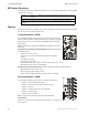
1. Product Description Options Remote Annunciator - RZA-4X The Remote Annunciator mounts on a standard single-gang box, and provides LED indication of the same functions as the Zone Relay Module. • Alarm/Alarm Pressure (red) • Alarm Pressure/Aux Supervisory (red) • Releasing Circuit 1 (red) • Aux Supervisory/Releasing Circuit 2 (red) RE-SOUND TONE SILENCE • System Trouble LED (yellow) A local trouble sounder and silence switch are also provided. All LED wiring is supervised for open conditions.
1. Product Description Specifications Specifications AC Power PDRP-1001 and PDRP-1001A: 110/120 VAC, 50/60 Hz, 1.2 amps PDRP-1001E: 220/240 VAC, 50/60 Hz, 0.6 amps Wire size: minimum #14 AWG with 600V insulation Battery (lead acid only) Maximum Charging Circuit: 27.6V, 1.5 amps Maximum Battery Capacity: 18 AH. Note: Batteries larger than 12 AH require Notifier BB-17 or other UL-listed external battery cabinet.
2. Installation Cabinet Mounting Carefully unpack the system and check for shipping damage. Select a suitable location in a clean, dry, vibration-free environment that is not subject to extreme temperatures. Locate the top of the cabinet approximately five feet above the floor with the hinge on the left. The panel must be easily accessible for maintenance; the hinged door requires a minimum clearance of 14 in. (35.56cm) to open.
2. Installation Cabinet Mounting The figure below shows the exterior dimensions and mounting hole locations for the cabinet backbox and dimensions of the optional trim ring: 14.625” (37.15cm) 5.375” (13.65cm) 16.125” (40.96cm) MS44-cabdim.cdr 16.00” (40.64cm) 4.75” (12.07cm) 1.00” (2.54cm) 14.50” (36.83cm) 12.50” (31.75cm) 1.00” (2.54cm) 9.50” (24.13cm) 1.5” (3.81cm) 14.625” (37.15cm) MS44-trimring.cdr 16.125” (40.
2. Installation Installing Optional Voltmeter/Ammeter Installing Optional Voltmeter/Ammeter To monitor battery voltage and battery charging current, a 4XMM Meter Module is required. To install the power meter module follow the steps below: Step Action 1 Cut the jumper wire labeled “AMP”. 2 Secure the module to the backbox with the hardware provided. Refer to Product Installation Drawing (PID) for detailed instructions. 3 Connect meter cable P2 to connector J2 on the main circuit board.
2. Installation Power Connections Power Connections ! WARNING: Do not apply any type power to this control panel until all connections have been made and verified. AC Connections Disconnect (open) the circuit breaker in the AC main breaker panel and tag it “Out of Service”. Note: Refer to "Power-Up Procedure" on page 30 before closing AC breaker. Primary power required for the PDRP-1001 and PDRP-1001A control panels is 110/120 VAC, 50/60 Hz, 1.2 amps and for the PDRP-1001E is 220/240 VAC, 50/60 Hz, 0.
2. Installation Power-limited Wiring Requirements Observe polarity when connecting the batteries. Connect the battery cable (p/n 75203 or 75202, depending on terminal size of battery) to terminal J9 on the main circuit board using the plug-in connector provided. Connect red wire to positive (+) terminal and black wire to negative (–) terminal on opposing batteries. Do NOT connect battery interconnect wire at this time. TB5 J2 AMP J9 MS44-BATconn.
2. Installation Initiating Device Circuits Initiating Device Circuits The control panel provides four (4) Initiating Device Circuits (#1, #2, #3 and #4) and they may be configured as either Style D (Class A) or Style B (Class B). Initiating devices include: Heat, Photoelectric and Ionization type detectors, Manual Pull Stations and Waterflow alarm devices. Note: Refer to the "Appendix B: Compatible Devices" on page 39 for compatible devices.
2. Installation Initiating Device Circuits Four-Wire Smoke Detector Connections A maximum of 200mA is available from the 24VDC Resettable Power circuit on TB1 (+24VR terminals). Any power that is drawn from the 24VDC Nonresettable Power on TB2 (+24VNR terminal) must be subtracted from available resettable power. See "Specifications" on page 12 and "Powering External Devices" on page 22. Note: Refer to the "Appendix B: Compatible Devices" on page 39 for suitable 4-wire smoke detectors.
2. Installation Output Circuits Output Circuits Notification Appliance Circuits The control panel provides two Style Z (Class A) or Style Y (Class B) Notification Appliance Circuits, which are supervised and power-limited. Each circuit is capable of 1.5 amps of current. Total current drawn from both NACs and both Releasing Circuits (see "Releasing Circuits" on page 21) cannot exceed 2.25 amps. Note: Refer to the "Appendix B: Compatible Devices" on page 39 for suitable devices.
2. Installation Output Circuits Releasing Circuits ! CAUTION: To prevent accidential discharge, connect releasing devices after initial panel tests are completed. The control panel provides two Style Y (Class B) Releasing Circuits, which are nonpower-limited. Note: All wiring must follow the requirements as specified under "Power-limited Wiring Requirements" on page 17. Each circuit is capable of 1.5 amps of current.
2. Installation Powering External Devices Alarm Relay Circuit One Form-C dry contact alarm relay is provided in the basic panel for controlling supplementary devices. Contacts are rated 2 amps at 30 VDC and 0.5 amps at 30 VAC (resistive) and are non-silenceable when an alarm occurs. Trouble Relay Circuit One Form-C dry contact trouble relay is provided in the basic panel for controlling supplementary devices. It is rated 2 amps at 30 VDC and 0.
2. Installation Optional Modules Optional Modules Overview The control panel has two module connectors - J5 (upper position) and J8 (lower position). Three modules are available for the panel and they can be used in any combination, including duplicate modules. The corresponding option jumper must be cut before installation of an optional module, to enable module supervision. • The 4XZM Zone Relay and the 4XTM Transmitter Modules can be installed in either position.
2. Installation Optional Modules Installation - Lower Position To install either the 4XTM, 4XZM or 4XLM module in the lower position follow these instructions: Step Action 1 Cut jumper ‘OPT2’ on main circuit board. 2 Remove the lower-right screw securing the main board to the lower rail. Replace with a stand-off and tighten securely. 3 Insert one stand-off into the other hole located on the right-side edge of the main board. Secure with nut and tighten securely.
2. Installation Optional Modules Setup and Configuration Transmitter Module - 4XTM Connect a Remote Alarm circuit, Remote Trouble circuit or a Municipal Box to the Transmitter Module as shown below. Polarities shown in activated positions. Note: Dummy load terminals 6 and 7 (4.7K, 1/4 W resistor) if Municipal Box is not connected. Note: Remote Alarm, Remote Trouble and Municipal Box wiring can leave the building.
2. Installation Optional Modules Zone Relay Module - 4XZM Note: The PAR-3 includes one (1) Zone Relay Module (4XZM). Relay #1 through #4 on this module will activate with outputs #1 through #4. For non-latching (silenceable) relay operation, cut the jumper “LATCH”. If this jumper is left intact, the relays will latch upon activation. To disconnect relays entirely, slide the disable switch to the right.
2. Installation Optional Modules LED Interface Module - 4XLM Connect the terminals on TB1 of the LED Interface Module to the corresponding terminals of the RZA4X Remote Annunciator. Make wiring connections with system power off. Maximum wire impedance is 50 ohm per wiring connection. TB1 The wiring of this module must follow the requirements as specified under "Power-limited Wiring Requirements" on page 17.
2. Installation Setting Mode of Operation Setting Mode of Operation Select operating mode by setting the SW1 DIP switches as described below. After any changes are made to the configuration of the switches, the panel must be reset. For Canadian use, refer to "Sprinkler Supervisory Tracking" on page 34. MS44-dipsw.
2. Installation Setting Mode of Operation Discharge Timer Select the desired discharge timer setting by setting DIP Switches 3, 4 and 5 accordingly. • For NFPA 13 and 15 applications timer must be set to “Disabled”. • For NFPA 16 applications timer may be set to “10 Minutes” or “15 Minutes”. Disabled 10 Minutes 15 Minutes Switch #3 OFF ON ON Switch #4 OFF ON ON Switch #5 OFF OFF ON Note: Timer will always start at Zone 2 normal to alarm transition.
2. Installation Power-Up Procedure Power-Up Procedure WARNING: Prior to energizing this panel, notify all personnel and authorities, including any personnel who may be working on, around, or near this unit. ! ! WARNING: Battery contains sulfuric acid which can cause severe burns to the skin and eyes and can destroy fabrics. If contact is made with sulfuric acid, immediately flush the skin or eyes with water for 15 minutes and seek immediate medical attention. CAUTION: Observe polarity of batteries.
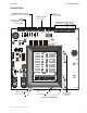
3. System Operation System Status LEDs Alarm, Trouble and Supervisory LEDs will flash on and off until the event(s) has been acknowledged (TONE or ALARM SILENCE), at which point the LED will illuminate steadily. AC POWER SYSTEM ALARM System Status LEDs ZONE 1 RELEASE ZONE 2 SUPERVISORY SYSTEM TROUBLE CIRCUIT TROUBLE ALARM SILENCED WATERFLOW SUPERVISORY POWER TROUBLE PEM2-panel1.
3. System Operation Control Switches TONE ALARM ALARM SYSTEM SILENCE SILENCE ACTIVATE RESET MS44-panel2.cdr Control Switches Figure 22 Control Panel Switches Tone Silence - Pressing this switch acknowledges alarms, troubles and supervisories. The panel has alarm and trouble resound with LED flash of new conditions. The flashing trouble LED(s) illuminate steadily on TONE SILENCE and the piezo turns off. A second trouble will resound the piezo. Trouble conditions are self-restoring.
3. System Operation Piezo Piezo The piezo (local buzzer) generates different tone patterns for different event conditions: • Alarm - Generates a steady tone, no pulse. • Trouble - Pulses one second on, one second off. Repeats 30 pulses per minute. • Supervisory - Pulses one-half second on, one-half second off. Repeats 60 pulses per minute. Supervisory Service Initiating Device Circuit #4 is always used for monitoring supervisory devices (such as valve tamper switches).
3. System Operation Last Event Recall Last Event Recall Last Event Recall allows the user to display the previous panel status. The Last Event Recall makes use of the four panel switches as follows: 1. Press and hold in the TONE SILENCE switch. 2. With the TONE SILENCE switch held in, press (in sequence) the SYSTEM RESET switch, the ALARM ACTIVATE switch, and then the ALARM SILENCE switch. 3. LEDs will light to indicate the last event recorded in the panel’s buffer. 4.
3. System Operation System Events Single Zone in Alarm (Cross Zone) Condition Upon actuation of a single-zone initiating device, a red alarm LED will illuminate to indicate whether Zone 1 or Zone 2 is in alarm. In addition to the LED, a single-zone alarm will activate the Alarm Relay; the piezo and NAC #1 will start sounding. In alarm condition, the piezo will generate a steady tone. The piezo can be silenced by pressing the trouble silence switch.
3.
Appendix A: Secondary Power Calculations Standby Battery Requirements The Standby Battery Current obtained in the table below represents the amount of current that must be supplied by the secondary power source (batteries) to sustain control panel operation for one hour. Note: The control panel will support the installation of one or two optional modules, including two of the same type of module. Only one 4XLM can be included in this count.
Appendix A: Secondary Power Calculations Calculating the Battery Capacity Calculating the Battery Capacity Use this table to determine the battery capacity required by the system. Standby Battery Current (from Table 1) [ ] amps Required Standby Time in Hours (typically 241, 602 or 903 hours) [ ] hrs X Standby Amp Hours = Enter: 0.25 for 5 minutes in alarm, or 0.50 for 10 minutes in alarm 1. 2. 3. 4.
Appendix B: Compatible Devices Two-wire Smoke Detectors, UL Listed Use the two-wire detectors listed below. Detector Model Standby Detectors Identifier Current per Zone (mA) Identifier Type Base Model System Sensor 1400 A Ionization n/a n/a 0.10 20 System Sensor 1451 A Ionization B401/B401B/ B406B A 0.12 15/15/1 System Sensor 1851DH A Ionization DH1851DC A 0.12 15 System Sensor 2400 A Photoelectric n/a n/a 0.
Appendix B: Compatible Devices Four-wire Smoke Detectors, UL Listed Four-wire Smoke Detectors, UL Listed Use the four-wire detectors listed below. Detector/Base Max Standby Max Alarm Current (mA) Current (mA) Type System Sensor 2424 Photoelectric 0.10 41 System Sensor 2424TH Photoelectric 0.10 41 System Sensor 2451 Photoelectric 0.10 39 System Sensor 2451TH w/B402 Base Photoelectric 0.10 39 Ionization 0.10 41 System Sensor 1424 System Sensor 1451 w/B402 Base Ionization 0.
Notification Appliances, UL Listed Appendix B: Compatible Devices Notification Appliances, UL Listed Control panels suppling Special Application (FWR, Filtered) power must use the Notification Appliances listed below. • Rated Voltage is nominal operating voltage • All currents are in millamperes and worst case average.
Appendix B: Compatible Devices Notification Appliances, UL Listed Rated Voltage Product FWR DC Filtered DC System Sensor SP101R24M Speaker/Strobe, 5” square grill 24VDC 125 75 System Sensor SP100W24MC Ceiling Speaker/Strobe, 8” round grill 24VDC 125 75 System Sensor MA12/24EH Multi Alert Horn with Mechanical Tone 12VDC/ 24VDC 20/64 38/43 System Sensor MAEH24LO Multi Alert Horn with Mechanical Tone/Strobe 24VDC 109 68 System Sensor MAEH24LOC Multi Alert Horn with Mechanical Tone/Strobe
Appendix B: Compatible Devices Door Holders, UL Listed Door Holders, UL Listed Use the Door Holders listed below. Current (mA) Model Type FM-980-24 Floor Mount, Single 68 FM-986-24 Wall Mount, Surface Wiring 68 FM-998-24 Wall Mount, Concealed Wiring 68 DH150A Floor Mount 96 DH154A Flush Mount 96 DH158A Surface Mount 96 Table 7 Door Holders 24 VDC Relays, UL Listed Use the Relays listed below.
Appendix B: Compatible Devices 24 VDC Relays, UL Listed Notes 44 PDRP-1001 Instruction Manual PN 50734:D0 04/06/01
Appendix C: NFPA Standard-Specific Requirements Minimum System Requirements The control panel has been designed for use in commercial, industrial, and institutional applications and meets the requirements for service under the National Fire Protection Association (NFPA) Standards outlined in this appendix. The minimum system components required for compliance with the appropriate NFPA standard are listed below. • Fire Alarm Control Panel.
Appendix C: NFPA Standard-Specific Requirements Digital Alarm Communicator/Transmitter - Noti-Fire 911AC Digital Alarm Communicator/Transmitter - Noti-Fire 911AC Note: This application is not FM approved Using the Noti-Fire 911AC DACT for connection to a Central Station Receiver or Protected Premises Receiving Unit. • AC Wiring for DACT/FACP must be connected to the same circuit. • If the unit is not mounted in the control panel’s backbox all connections must be in conduit, less than 20 ft. (609.
Universal Digital Alarm Communicator - 411UDAC Appendix C: NFPA Standard-Specific Requirements Universal Digital Alarm Communicator - 411UDAC The following figure illustrates an example of Central Station/Remote Station Receiver or Protected Premises Receiving Unit reporting using a 411UDAC. The relay contacts of the MRP-4424 may be used to trip any dialer listed for Central Station/Remote Station services. For additional information refer to the Instruction Manual for the 411UDAC.
Appendix C: NFPA Standard-Specific Requirements Local Energy Municipal Box Local Energy Municipal Box Using the 4XTM Transmitter Module for connection to a Local Energy Municipal Box. • The Municipal Box circuit supervises for ground faults and opens (i.e. missing wire) but not for direct short between two wires. It is not a power-limited circuit. • This application is not suitable for separate transmission of sprinkler supervisory or trouble conditions.
Remote Station Receiver - RS82-9 Using the 4XTM Transmitter Module for connection to a Fire•Lite RS82-9 Remote Station Receiver. • Intended for connection to a polarity reversal circuit of a remote station receiving unit having compatible ratings. • All connections are power-limited and supervised with the exception of the reverse polarity loop. • Supervision of the loop is the responsibility of the receiver.
Appendix C: NFPA Standard-Specific Requirements Remote Station Receiver - RS82-9 Notes 50 PDRP-1001 Instruction Manual PN 50734:D0 04/06/01
Appendix D: Testing & Maintenance Testing Inspection Perform the following prior to applying power to the system. • Check the actual wiring hookup with the wiring diagrams. • Insure that no pieces of wire have fallen into the circuitry. • Check for missing or damaged parts. Alarm Test An initial alarm test should be conducted following installation to determine that all parts of the system are functioning properly.
Appendix D: Testing & Maintenance Troubleshooting Table 9 Troubleshooting Table Symptom System trouble LED ON Problem Circuit trouble LED ON Notification appliance circuit trouble Any of the right column yellow LEDs flashing Initiating zone open circuit trouble Any of the right column yellow LEDs steady ON Zone disable Missing or Disconnected AC Power LED ON Power trouble LED ON Battery trouble Batt yellow Low or LED ON damaged battery Ground fault trouble Earth yellow LED ON Yellow LED on 4X
Index Index Numerics 110/120 VAC 12 220/240 VAC 12 411UDAC 45, 47 4XLM LED Interface Module 11, 23 4XMM Meter Module 11, 15 4XTM Transmitter Module 10, 23, 45, 4XZM Zone Relay Module 10, 23 911AC DACT 45, 46 A AC branch circuit 47 AC power 31, 47, 51 accidential discharge 21 acknowledge 32 additional equipment 45 alarm 31, 47 Alarm Relay 35 alarm relay 22, 51 allowable resistance 19 ammeter 11 annunciator wiring 11 audible alarm 51 authority having jurisdiction 51 B backbox 13 backbox rail 13, 14 Batter
Index inspection 51 interconnect wire, battery 30 Interface Module 11 interruption of circuits 34 National Electrical Code, Article 760 16 National Fire Protection Association 45 negative 17 NFPA 51 NFPA standards 45 non-latching 26, 32 nonpower-limited 17, 21, 26 nonresettable power 19, 22 non-silenceable service 20 Notification Appliance Circuit 32 Notification Appliances 45 J J1 connector 13, J2 Connector 15 J3 Connector 15 J9 Connector 17 JP1 jumper 47 jumper 23, 24 LATCH 26 14 O opens 48 operating
Index resettable power 19, 22 resistance, allowable 19 resistor 47 resound 32 reverse polarity 25 reverse polarity circuit 10 reverse polarity loop 49 RS82-9 Remote Station Receiver 45, RZA-4X Remote Annunciator 11 S second alarm 35 Secondary Power 30 secondary power source 37 self-restoring 32 separate transmission 48 short circuit 33 silence switch 11 Single Hazard 28 Slide-in paper labels 11 solenoid valve 35, 51 Split Release 28 sprinkler 33, 34 sprinkler supervisory 48 Standby Battery Current 37 stand
Limited Warranty System Sensor® warrants its products to be free from defects in materials and workmanship for eighteen (18) months from the date of manufacture, under normal use and service. Products are date stamped at time of manufacture. The sole and exclusive obligation of System Sensor® is to repair or replace, at is option, free of charge for parts and labor, any part which is defective in materials or workmanship under normal use and service.