
User manual


D100-68-00 6 I56-1147-12R
24V
120
VA
C
220/240
VAC
9
10
A
B C
AVAILABLE POWER INPUTS
ALARM AUXILIARY CONTACTS
FOR F
AN SHUTDOWN, ETC.
16
6
17
7
18
8
N.C.
C.
N.O
.
N.O.
C.
N.C
.
ALARM AUXILIARY CONTACTS
S
HOWN IN
ST
ANDBY. CONTACTS TR
ANSFER DURING
ALARM AS IN
DICATED BY THE ARROWS
.
SUPER
VISORY TROUBLE CONTAC
TS
TROUBLE
C
ONT
ACTS CLOSE
D
IN ALARM AND STANDBY.
CONTAC
TS OPEN
W
HILE DETECTOR PC
B
OR POWER IS
RE
MO
V
ED OR WHEN TAMPER
F
EATURE TIMES OUT. O
PEN
CONTAC
TS SIGNAL TROUBLE COND
ITION TO
P
ANEL
.
24V
220/240
VAC
9 1
0
A B
C
AVAILABLE POWER INPUTS
ALARM AUXILIARY CONTACTS
FOR
F
AN SHUTDOWN
, ETC.
1
6 6
17
7 1
8
8
N.C.
C.
N.O.
N.O.
C.
N.C.
ALARM AUXILIARY CONTACTS
S
HOWN IN
STANDBY. CONTACTS TR
ANSFER DURING
AL
ARM
AS INDICATED BY THE
A
RROWS
.
SUPERVISORY TROUBLE CONTACTS
TROUBLE CONTACTS
C
LOSED IN ALARM AN
D
STAN
D
BY
.
CONTACTS OPEN
W
HILE
D
ET
E
C
TOR
P
C
B OR POWER IS
RE
MO
VED OR WHEN TAMPER F
EATURE TIMES OUT. OPE
N
CONTACTS SI
GNAL TROU
B
LE
CONDITION TO
P
ANEL
.
14
3
3
14
4
5
ALARM
INITIATION
CONTACTS
CONTACTS
S
HOWN
OPEN IN ST
ANDBY.
CONTACTS CLOSE
IN AL
ARM.
4
5
ALARM
INITIATION
CONTACTS
CONTACTS
S
HOWN
OPEN IN STANDB
Y.
CONTACTS CLOSE
IN
ALARM.
AL
ARM
INITI
ATION
LOOP
UL LISTE
D 4-WIRE
CONTROL
P
ANEL
FIRST
DETECTOR IN
T
HE LOOP
DH100AC
DCP
LAST DETECTOR IN
T
HE LOOP
DH100AC
DCP
EOL RESISTOR
SPECIFIED BY
PANEL MANUFACTURER
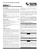
CONNECT POWER SOURCE
TO APPROPRIATE TERMINALS
OF EACH DETECTOR. SEE
SPECIFICATIONS FOR
ADDITIONAL POWER SUPPL
Y
INFORMATION.
FOR WIRIN
G OF AUXILIARY
DEVICES, REFER TO
MANUFACTURER
'S
INSTALLATION IN
STRU
CTIONS
OR CONTACT MANUFACTURER
.
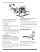
NOTE:
THE SUPERVI
SORY RELAY
NOW
PROVIDES
A "FORM C" CONTACT FOR
CUSTOMIZED APPLI
CATIONS
.
FOR STANDARD APPLI
CATIONS, ONL
Y
THE "NO" CONTACT IS USE
D
POWER INPUTS ACCEPT
24 VDC, 24 VAC 50-60 H
Z,
120 VAC 50-60 HZ, OR
220/240 VAC 50-60 HZ.
CONNECT POWER SOURCE
TO APPROPRIATE TERMINALS
OF EACH DETECTOR.
AUX. CONTAC
T RATINGS
10A
@
3
0
V
D
C RESISTI
VE
10A
@
2
50 VAC
100
mA MINIMUM @ 5 VDC
NOT INTEN
DED FOR
CONNECTION TO CONTROL
PANELS
.
TROU
BLE CONTACT RATING
2.0
A
@
3
0 VDC resistive
2.0
A
@
1
25 VAC resistive
+
–
12
0
VA
C
CAUTION
Do not loop wire under terminals when wiring detectors. Break wire runs to provide system supervision of connections.
Figure 8. Wiring diagram for DH100ACDCP to APA451:
A78-2352-27
Figure 7. System wiring diagram for 4-wire duct smoke detectors:
4-Wire Wiring to APA451
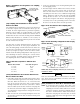
Figure 9. Wiring diagram for DH100ACDCP to
RTS451KEY and interconnect feature:
15
19
14
3
20
2
11
2
6
1
Alarm Signal
Aux. Power +
Sup. N. O.
Sup. COM
Aux. Power –
Reset
Test
(Red LED) Alarm
(Green LED)
Power
DH100ACDCP
RTS451/RTS451KEY
5
4
3
*
For RTS451KEY
only without a
control panel.
*
Important Interconnect Notes
• When using the interconnect feature, all in-
terconnected units must be powered with
the same, independent supply.
• Polarity must be maintained throughout the
interconnect wiring. Connect terminal 12 on
unit 1 to terminal 12 on unit 2 and so on.
Similarly, connect terminal 1 on unit 1 to ter-
minal 1 on unit 2 and so on.
Figure 10. Multiple fan shutdown (interconnect):
1
6
12
16
A
B
C
FAN
CONTROL
SYSTEM
CONTROL
POWER OR
THERMOSTAT
1
6
12
16
A
B
FAN
CONTROL
SYSTEM
CONTROL
POWER OR
THERMOSTAT
DETECTOR 1
C
DETECTOR
2
1
6
12
16
A
B
FAN
CONTROL
SYSTEM
CONTROL
POWER OR
THERMOSTAT
C
DETECTOR
3
1
12
–
+
NEXT
DETECTOR