
Owner's manual


Front Panel Control Switches
1 The PDRP-1002/PDRP-1002E
The PDRP-1002 PN 51135:A 03/11/99 7
Front Panel Control Switches
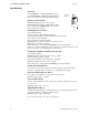
Switch 1 Tone Silence
Switch 2 Alarm Silence
Switch 3 Alarm Activate
Switch 4 System Reset
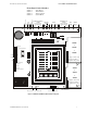
Figure 1 PDRP-1002/PDRP-1002E Installation Diagram
B+ A+ A- B-B+ A+ A- B-
B+ A+ A- B-
B+ A+ A- B-
TB1
TB2
TB3
TB4
BATT
EARTH
JP 1
SUPV 2
GEN ALM2
J1
J2
J9
J3
NO DACT
DACT
SW1
123456
O
N
-
+
NO NC C NO NC C
B+ B-
B+ B-
B+ A+ A- B-
B+ A+ A- B-
+ -
+ -
+24VNR
+24VR
TB5
+24VU
*
*
+ -
24 VVU
RMS-REGULATED
24 VR
REGULATED
RESETTABLE
24 VNR
REGULATED
NON-RESETTABLE
1234
Notification Appliance
Circuits
Class A (Style Z)
Class B (Style Y)
Releasing
Circuits
Relays
TroubleAlarm
Contacts Contacts
1234
Initiating Device
Circuits
Class A (Style D)
Class B (Style B)
Abort
Switch
Manual
Release
4XTM
or
4XLM
or
4XZM
4XTM
or
4XLM
or
4XZM
*Jumper “OPT 1” must
be cut if a module is
installed in this position
*Jumper “OPT 2” must
be cut if a module is
installed in this position
OPT 1
OPT 2
Micro Fail LED
Abort Option
Abort Option
Delay Timer
Cross Zone
Supervisory
Delay Timer
Ground Fault LEDBattery Fail LED
Batteries
Optional Ammeter
Connection
Transformer
AC Circuit Breaker
Optional
VoltmeterConnection
4XRP1002.cdr
Ground
Neutral
Hot