PDRP1002.CD System Sensor 3825 Ohio Avenue St.
Installation Precautions – Adherence to the following will aid in problem-free installation with long-term reliability: WARNING - Several different sources of power can be connected to the fire alarm control panel. Disconnect all sources of power before servicing. Control unit and associated equipment may be damaged by removing and/or inserting cards, modules, or interconnecting cables while the unit is energized.
The PDRP-1002 PN 51135:A 03/11/99 3
The PDRP-1002 PN 51135:A 03/11/99
NFPA Standards This control panel complies with the following NFPA standards: NFPA 12 CO2 Extinguishing Systems (High Pressure Only) NFPA 12A Halon 1301 Extinguishing Systems NFPA 12B Halon 1211 Extinguishing Systems NFPA 72 Central Station Signaling Systems (Automatic, Manual, and Waterflow).
1 The PDRP-1002/PDRP-1002E Input Circuits 1 The PDRP-1002/PDRP-1002E Features • • • • • • • • • • • • • • • • • • • • • • • • • • • • • • • • • • Microprocessor-controlled Power-limited on all circuits except Municipal Box output Alarm and trouble resound Four Class A (Style D)/Class B (Style B) Initiating Device Circuits Two Class A (Style Z)/Class B (Style Y) Notification Appliance circuits Two Class B (Style Y) Release Circuits General alarm and trouble relays Optional module for 4 zone/function relay
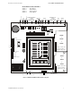
1 The PDRP-1002/PDRP-1002E Front Panel Control Switches Front Panel Control Switches + - 24 VNR REGULATED NON-RESETTABLE 24 VVU RMS-REGULATED +24VU 24 VR REGULATED RESETTABLE Switch 1 Switch 2 Switch 3 Switch 4 +24VR +24VNR + - + - Tone Silence Alarm Silence Alarm Activate System Reset Notification Appliance Circuits Class A (Style Z) Class B (Style Y) 1 2 B+ A+ A- B- B+ A+ A- B- Releasing Circuits Initiating Device Circuits Class A (Style D) Class B (Style B) Relays Alarm Trouble 3
1 The PDRP-1002/PDRP-1002E Transmitter Module (4XTM - NOTIFIER) Optional Boards The PDRP-1002/PDRP-1002E has mounting slots for two option boards. Any two of the three option modules may be installed. Transmitter Module (4XTM - NOTIFIER) The Transmitter Module provides a supervised output for local energy municipal box transmitter (for NFPA 72 Auxiliary Fire Alarm System) and alarm and trouble reverse polarity circuits (for NFPA 72 Remote Station Fire Alarm System).
Transmitter Module (4XTM - NOTIFIER) 1 The PDRP-1002/PDRP-1002E Transmitter Module (4XTM - NOTIFIER) For Local Energy Municipal Box service (NFPA 72 Auxiliary Fire Alarm System) Supervisory current: 5.0 mA Trip current: 0.35 amps. (Subtracted from Notification Appliance power) Coil Voltage: 3.65 VDC Coil resistance: 14.
1 The PDRP-1002/PDRP-1002E AC Power Specifications AC Power For the PDRP-1002: 120 VAC, 50/60 Hz, 1.2 amps For the PDRP-1002E: 220/240 VAC, 50 Hz, 0.6 amps Wire size: minimum #14 AWG with 600V insulation AC Circuit Breaker Battery (lead acid only) Acctbrkr.cdr Maximum Charging Circuit: 27.6V, 1.5 amps Maximum Battery Capacity: 15 AH. (Batteries larger than 12 AH require NOTIFIER #BB-17 or other UL listed external battery cabinet.
1 The PDRP-1002/PDRP-1002E RMS Regulated Power Cabinet Door Backbox Door Backbox = 5.375 in. (136.53 mm) Backbox = 4.750 in. (120.65 mm) = 14.625 in. (371.48 mm) = 14.5 in. (368.3 mm) = 16.125 in. (409.58 mm) = 16 in. (406.4 mm) 1.5 in (38.1 mm) TR-4XR RUBY RD STEEL 16 GA. 14.594 in. (370.69 mm) RPCABDIM.cdr 16.094 in. (408.
2 System Operation RMS Regulated Power 2 System Operation ! WARNING:When used for CO2 releasing applications, observe proper precautions as stated in NFPA 12. Do not enter the protected space unless physical lockout and other safety procedures are fully completed. Do not use software disable functions in the panel as lockout.
2 System Operation RMS Regulated Power Control Switches Tone Silence 4XPTL.cdr Acknowledge alarms, troubles and supervisories. The panel has alarm and trouble resound with LED flash of new conditions. The flashing trouble LED(s) illuminate steadily on TONE SILENCE and the piezo sounder silences. A second trouble will resound the piezo. The piezo has three sounds for alarm, trouble, and supervisory. Trouble conditions are self-restoring. Alarms latch and require RESET to clear.
2 System Operation RMS Regulated Power Supervisory Output circuit #4 is used as an input for monitoring supervisory devices such as valve tamper switches (note that SW1 DIP switch #2 must be set “ON” -- see section “Setting Mode of Operation”) By setting Switch short circuit on this input (activation of a N.O. contact) will cause the supervisory LED to flash. The piezo sounder will generate a unique sound. TONE SILENCE will silence the piezo and cause the LED to illuminate steadily.
3 Installation Procedure UL Power Limited Wiring Requirements 3 Installation Procedure General Carefully unpack the system and check for shipping damage. Mount the cabinet in a clean dry, vibration-free area in which extreme temperatures are not encountered. The location should be readily accessible with sufficient room for easy installation and maintenance. Locate the top of the cabinet approximately five feet above the floor with the hinge mounting on the left.
3 Installation Procedure Zones Initiating Device Circuits Zones Wire all alarm initiating devices sequentially for proper supervision. Initiating devices include: heat, photoelectric, and ionization type detectors; and waterflow alarm devices. Refer to the Compatibility Chart in Appendix B. Note: • Observe polarity when connecting polarized devices. • All circuits are supervised and power limited. • Leave Dummy Load (provided) on all unused circuits. Class B (Style B) Initiating Device Circuit 4.
3 Installation Procedure Zones 4-Wire Smoke Detector Connections Refer to the Device Compatibility Document for suitable 4-wire smoke detectors. 24 VDC (+) 24 +VDC+ (+) Red Common (-) Common (-) Black + - + - - IDC (+) + + - - - IDC (+) IDC (-) + + - - IDC (-) UL listed 24 VDC Four-wire Smoke Detectors 1 2 + - 3 4 Listed Power Supervision Relay TB4 +24VR A maximum of 200mA is available from the +24VDC 4-wire smoke detector power circuit on TB1 terminals 3 and 4.
3 Installation Procedure Notification Appliance Circuits Output Circuits Notification Appliance Circuits This control panel can provide two Class A (Style Z)/Class B (Style Y) Notification Appliance Circuits and two Class B (Style Y) Releasing Circuits (see section “Setting Mode of Operation” for DIP switch configuration). Each circuit is capable of 1.5 amps of current. Total current drawn from all four circuits cannot exceed 2.25 amps. Refer to the Compatibility Chart.
3 Installation Procedure Alarm Relay Alarm Relay One Form-C dry alarm contact is provided in the basic panel for controlling supplementary devices. It is rated 2 amps at 30 VDC and 0.5 amps at 30 VAC (resistive), and is non-silenceable when an alarm occurs. See below for terminal location. Trouble Relay One Form-C dry trouble contact is provided in the basic panel for controlling supplementary devices. It is rated 2 amps at 30 VDC and 0.
3 Installation Procedure AC Power AC Power Primary power required for the PDRP-1002 panel is 120 VAC, 50/60 Hz, 1.2 amps and primary power for the PDRP-1002E is 220/240 VAC, 50 Hz, 0.6 amps. Overcurrent protection for this circuit must comply with Article 760 of the National Electrical Code (NEC) and/or local codes. Use #14 AWG (2.00 mm2)or larger wire with 600 volt rating. Battery Power Observe polarity when connecting battery.
3 Installation Procedure Voltmeter/Ammeter Optional Modules The fire control panel has two module connectors - J5 and J8. Three modules are available for the panel and they can be used in any combination, including duplicate modules. The corresponding option jumper must be cut before installation of an optional module.
3 Installation Procedure Installing Option Modules Installing Option Modules Insert the two stand-offs (provided) into the holes located on the right-side edge of the main board. Carefully align the pins on the main board with J1 and/or J2 on the option board. Insert screw through the option board until it is secured on the stand-offs. Affix the terminal identification labels provided with the option modules as shown below. (Part # 42050) Stand-offs) Main Board 4XOPTNBD.cdr 4XSTNOFF.
3 Installation Procedure Transmitter Module - 4XTM (NOTIFIER) Transmitter Module - 4XTM (NOTIFIER) Polarities shown in activated positions. The wiring of this module must follow the requirements as specified in the “General” section, “UL Power Limited Wiring Requirements.” 1 2 3 4 5 6 7 + } Remote Alarm + Remote Trouble -} Power Limited Circuit No Connection + Municipal Box* -} Non-Power Limited Circui TBL Jumper 4XTBa.cdr Disconnect LED * Dummy load terminals 6 and 7 (4.
3 Installation Procedure Zone Relay Module - 4XZM (NOTIFIER) Zone Relay Module - 4XZM (NOTIFIER) Non-power limited and power limited wiring must have a minimum distance of 0.25 in. (6.35 mm) wire to wire. If this module is used to drive non-power limited and power limited circuits, please follow the instructions below. 4XZMA.cdr Relay #1 through #4 will activate with Output #1 through #4 and remain latched unless jumper “LATCH” is cut.
3 Installation Procedure LED Interface Module - 4XLM (NOTIFIER) LED Interface Module - 4XLM (NOTIFIER) The wiring of this module must follow the requirements as specified in section”UL Power Limited Wiring Requirements.” +24V Out#1 Out#2 Out#3 Out#4 System Trouble Sound Resound 4XLMa.cdr 1 2 3 4 5 6 7 8 RZA4Xfr.cdr RZA4XBX.cdr Connect to corresponding terminals of RZA-4X Remote Annunciator. Side View Front View Single-gang Box Note: Make wiring connections with system power off.
3 Installation Procedure DIP Switch Setting Mode of Operation DIP Switch 4XRPDIPS.cdr The DIP switch is located at the bottom of the PDRP-1002/PDRP-1002E main board. To set a switch to the “ON” position, slide the switch up until it stops. The flushsurface switches are designed to prevent accidentally changing a switch setting and may therefore require use of a pen or screwdriver to set them.
3 Installation Procedure Output 4 Supervisory/Releasing Service Output 4 Supervisory/Releasing Service Set the function of Output 4 via SW1 DIP switch 2. Switch 2 OFF ON Output 4 will function as a solenoid releasing circuit. This circuit will be a non-power limited circuit in this mode. Output 4 will function as a supervisory input circuit. A short condition on this circuit will illuminate the Supervisory LED and sound the supervisory tone on the piezo.
Appendix A: Power Calculations Standby Battery Requirements Appendix A: Power Calculations Standby Battery Requirements The Standby Battery Current figure obtained in the following table (Table 1) represents the amount of current that must be supplied by the secondary power source (batteries) to sustain control panel operation for one hour. Basic Control Panel 88 mA Control panel with AC power off, System Trouble LED and audible trouble sounder on.
Appendix A: Power Calculations Ampere-Hour Calculations Ampere-Hour Calculations Standby Battery Current Convert the total from Table 1 to amps and enter here StandbyTime 24, 60, or 90 hours hours = Standby amp/hours Enter 0.25 for 5 minutes in alarm + or 0.5 for 10 minutes in alarm Alarm amp/hours Add Standby and Alarm amp/hours = Total amp/ hours needed amps X Table 2 Ampere-Hour Calculations Select a battery with an equal or greater amp/hour rating than the figure obtained in Table 2.
Appendix B: Device Compatibility FM-Approved Releasing Devices Appendix B: Device Compatibility Smoke Detector/Base Detector Type Max Standby Current (mA) Max Alarm Current (mA) System Sensor 2424 Photoelectric 0.10 41 System Sensor 2424TH Photoelectric 0.10 41 System Sensor 2451 Photoelectric 0.10 39 System Sensor 2451TH (with/B402B Base) Photoelectric 0.10 39 System Sensor 1424 Ionization 0.10 41 System Sensor 1451 (w/B402B Base) Ionization 0.
Appendix B: Device Compatibility FM-Approved Releasing Devices 8 in. orifice. Solenoid Group [C] Star Sprinkler Corp. Solenoid P/N 5550, 24 VDC, part of Model D deluge valve. Kidde-Fenwal Electric Control Head P/N 890181; 24V, 2.0 Amps Kidde-Fenwal Electric Control Head P/N 899175; 24V, 2.0 Amps Kidde-Fenwal Electric Control Head Stackable (XP) P/N 48650001; 24V, 0.2 Amps Kidde-Fenwal Electric and Cable Op Control Head (XP) P/N 897494; 24V, 1.
Appendix B: Device Compatibility FM-Approved Releasing Devices SYSTEM SENSOR Rated Voltage² FWR DC Filtered DC System Sensor MA-12/24D Electronic Sounder 24VDC 73 46 System Sensor SS24 Strobe 24VDC note 5 30 System Sensor SS24LO Strobe 24VDC 45 25 System Sensor SS24LOC Ceiling Strobe (SS24LOBC - beige) 24VDC 45 25 System Sensor SS24M Strobe 24VDC 125 75 System Sensor SS24MC Ceiling Strobe 24VDC 125 75 System Sensor MASS24D Electronic Sounder/Strobe 24VDC 118 71 System Senso
FM-Approved Releasing Devices Appendix B: Device Compatibility System Sensor SP1R241575ADA Speaker/Signaling Strobe 24 VDC 120 93 System Sensor V4R2415ADA Speaker/Signaling Strobe 24VDC 90 75 System Sensor V4R2475ADA Speaker/Signaling Strobe 24VDC 200 170 System Sensor V4R24110ADA Speaker/Signaling Strobe 24VDC 245 210 System Sensor V4R241575ADA Speaker/Signaling Strobe 24 VDC 120 93 System Sensor SP100W24LOC Ceiling Speaker/Strobe, 8" round grille 24VDC 45 25 System Sensor SP101R2
Appendix B: Device Compatibility FM-Approved Releasing Devices System Sensor P2475 SpectrAlert Horn/Strobe3 24VDC 215 180 System Sensor P24110 SpectrAlert Strobe3 24VDC 265 214 System Sensor RP1215ADAARetrofit Strobe Plate 12VDC 200 170 System Sensor RP121575ADAARetrofit Strobe Plate 12VDC 240 255 System Sensor RP2415ADAARetrofit Strobe Plate 24VDC 90 75 System Sensor RP241575ADAARetrofit Strobe Plate 24VDC 120 93 System Sensor RP2475ADAARetrofit Strobe Plate 24VDC 200 170 Syst
Appendix B: Device Compatibility FM-Approved Releasing Devices Number of Detectors Per Zone Model Det.
Appendix C: NFPA Standard-Specific Requirements FM-Approved Releasing Devices Appendix C: NFPA Standard-Specific Requirements The PDRP-1002/PDRP-1002E has been designed for use in commercial, industrial, and institutional applications and meets the requirements for service under the National Fire Protection Association (NFPA) Standards outlined in this appendix. The minimum system components required for compliance with the appropriate NFPA standards are listed below.
Appendix C: NFPA Standard-Specific Requirements NFPA 72 Signaling Systems for Central Station Service NFPA 72 Signaling Systems for Central Station Service (Protected Premises Unit) and Remote Station Fire Alarm System (Protected Premises Unit) NOTI•FIRE 911AC DACT* - for connection to a Central Station Receiver or Protected Premises Receiving Unit. This unit must be installed as illustrated below. For additional information on the 911AC, refer to document 74-06200-005.
Appendix C: NFPA Standard-Specific Requirements NFPA 72 Signaling Systems for Central Station Service Using the MS-5012 as a DACT 1) Reference the MS-5012 manual for additional information. 2) Program the MS-5012 for slave applications. 3) The PDRP-1002/PDRP-1002E is not suitable for transmission of a supervisory signal to the DACT.
Appendix C: NFPA Standard-Specific Requirements NFPA 72 Auxiliary Fire Alarm System NFPA 72 Auxiliary Fire Alarm System All connections are power limited and supervised. This application is not suitable for separate transmission of sprinkler supervisory or trouble conditions. Note: Maximum loop resistance allowed for wiring from control panel to Municipal Box is 3 ohms. + FIRE Municipal Box Circuit AUXPROSS.
Appendix C: NFPA Standard-Specific Requirements NFPA 72 Remote Station Fire Alarm System NFPA 72 Remote Station Fire Alarm System Intended for connection to a polarity reversal circuit of a remote station receiving unit having compatible ratings. All connections are power limited and supervised with the exception of the reverse polarity loop. Supervision of the loop is the responsibility of the receiver. N.C.2 DRY SUPPLEMENTARY CONTACTS, RATED 3A, 120 VAC RESISTIVE 3A, 30 VDC RESISTIVE N.O.2 POLE 2 N.C.
Appendix C: NFPA Standard-Specific Requirements NFPA 72 Remote Station Fire Alarm System Troubleshooting Table SYMPTOM PROBLEM Circuit trouble LED on Any of the right column yellow LEDs flashing Any of the right column System trouble LED on yellow LEDs steady on SOLUTION 1. Check TB2 for proper connections. (TB3 for 4XB panels) 2. Remove all field wiring and install dummy ELR at output circuit. Check for supervisory voltage across it. (Normal -2.3 V).
Appendix C: NFPA Standard-Specific Requirements NFPA 72 Remote Station Fire Alarm System Notes 42 The PDRP-1002 PN 51135:A 03/11/99
Appendix C: NFPA Standard-Specific Requirements NFPA 72 Remote Station Fire Alarm System Notes The PDRP-1002 PN 51135:A 03/11/99 43
Appendix C: NFPA Standard-Specific Requirements NFPA 72 Remote Station Fire Alarm System Limited Warranty System Sensor® warrants its products to be free from defects in materials and workmanship for eighteen (18) months from the date of manufacture, under normal use and service. Products are date stamped at time of manufacture.