
User's Manual

D690-03-00 2 I56-2769-003R
Candela Selection for P, S, PC, & SC series models
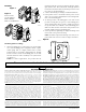
For strobe candela selection, adjust the slide switch located
on the rear of the product while watching the viewing win-
dow under the reflector on the front of the unit. Use Table
1 to determine current draw at various candela settings.
Table 2 can be used to derate the candela rating for low
temperature operation. Tables 3 & 4 can be used to deter-
mine strobe light output at various viewing angles.
NOTE: SpectrAlert products set at 15 and 15/75 candela au-
tomatically work on either 12V or 24V power supplies. The
products are not listed for 12V operating voltages when set
to any other candela settings.
Table 1. Current Draw (mA)
Candela
8–17.5 Volts 16–33 Volts
DC FWR DC FWR
Strobe
(Standard
Candela
Range)
15 123 128 66 71
15/75 142 148 77 81
30 NA NA 94 96
75 NA NA 158 153
95 NA NA 181 176
110 NA NA 202 195
115 NA NA 210 205
Strobe
(High
Candela
Range)
135 NA NA 228 207
150 NA NA 246 220
177 NA NA 281 251
185 NA NA 286 258
Table 2.
Listed candela rating Candela rating at –40°F
15 cd
See Note
15/75 cd
30 cd
75 cd 9.8
95 cd 16.2
110 cd 29.7
115 cd 41.4
135 cd 44.6
150 cd 49.5
177 cd 81.4
185 cd 72.2
NOTE: The 15, 15/75, and 30 cd settings are not intended
for use at temperatures below 32°F.
Table 3. Horizontal Plane Light Distribution for
Wall and Ceiling Applications
Horizontal Angle % of rated light output
0 100
45 75
90 25
Table 4. Vertical Plane Light Distribution
for Wall Applications
Vertical Angle % of rated light output
0 100
45 34
90 12
Horn Selection for P, PC, & H series models
Horn setting selection is accomplished by using the rotary
switch on the back of the product (see Table 5). The current
draw for various horn settings for horn and 4-wire horn/
strobe products is listed in Table 6. The current draw for
various horn and candela settings for 2-wire horn/strobe
products (P2 series) is shown in Table 7 & 8. The sound
measurements for various horn settings are shown in Table
9 for horn and horn/strobe products.
Table 5. Horn Patterns
Setting Repetition Rate dB Out
1 Temporal horn High
2 Temporal horn Medium
3 Temporal horn Low
4 Normal horn High
5 Normal horn Medium
6 Normal horn Low
7 Externally coded High
8 Externally coded Medium
9 Externally coded Low
NOTE: In positions 7, 8, and 9, temporal coding must be
provided by the NAC. If the NAC voltage is held constant,
the horn output will remain constantly on. Positions 7, 8,
and 9 are not available on 2-wire horn/strobe products.
Table 6. Horn Current Draw (mA)
Sound Pattern dB
8–17.5 Volts 16–33 Volts
DC FWR DC FWR
Temporal High 57 55 69 75
Temporal Medium 44 49 58 69
Temporal Low 38 44 44 48
Non-temporal High 57 56 69 75
Non-temporal Medium 42 50 60 69
Non-temporal Low 41 44 50 50
Coded High 57 55 69 75
Coded Medium 44 51 56 69
Coded Low 40 46 52 50
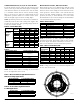
NOTE: Ceiling products have their maximum brightness on
the two axes shown below.
A0351-00