
Smoke Alarm User Manual


D500-08-00 9 I56-512-07R
Both Types Of Units
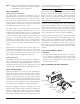
16. Reinstall the detector housing.
17. Restore power to the system.
18. Put detector into alarm using appropriate method
described in STEP 7. PERFORM DETECTOR CHECK
(page 7 of this manual).
19. Notify the proper authorities that testing has been
completed and the smoke detector system is again
operational.
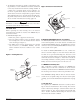
20. Other checks that should be made during mainte-
nance procedures:
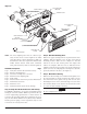
–Holes or cracks in duct work near vicinity of detec-
tor
–Air leaks where detector housing or sampling tubes
are attached to duct
–Dust accumulations in or on sampling tubes
–Wiring terminal screw tightness
Accessories Part No.
Remote LED RA400ZA
Remote Test Station RTS451/RTS451KEY
Piezo Alert Sounder PA400
Replacement Filters F36-05-00
Magnet M02-04-00
End Plug For Sampling Tube P48-21-00
Installation Kit (Parts bag) A2650-01
Ionization Replacement Screen RS14
Sensitivity Test Kit MOD400
Ionization Cover Removal Tool CRT400
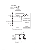
Programming Specifications/Requirements for
Intelligent System Control Panels
CAUTION
The 1551 and 2551 models can be used with the DH500 if
the following constraints are observed.
There is a limit to the number of devices per zone that can
have their LEDs latched ON. The actual number of devices
is determined by the control panel and its ability to supply
LED current. Refer to the equipment manual supplied by
the control panel manufacturer for details.
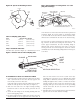
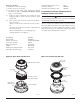
REMOVABLE HEAD COVER
CLEANABLE SCREEN
HEAD COVER
REMOVAL SLOT
TEST SLOT
VANED CHAMBER
P/N RS24 (W/O THERMAL)
H0261-00
Figure 10. Photo head exploded view:
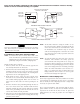
H0296-00
HOUSING
LOCK PRONGS
REMOVABLE SCREEN
(P/N RS14)
REMOVABLE
COVER
FOR
CLEANING
HEAD COVER
LOCK PRONGS
Figure 11. Ion head exploded view: