
Smoke Alarm User Manual


D500-08-00 8 I56-512-07R
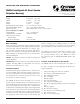
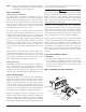
Step 8. Install the Cover
Install the cover using the four screws. Be certain filters are
installed as specified in Step 6. Make sure that the cover fits
into the base groove and that all gaskets are in their proper
positions. Tighten the four cover screws to 10 in/lbs.
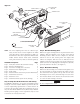
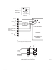
Step 9. Perform the Final System Check
Place the magnet in position as shown in Figure 7. The
LEDs on the detector should light. Any accessory LED(s)
will also light. The system control panel should indicate an
alarm condition.
Periodic Maintenance Requirements
Air duct smoke detectors should be maintained at least
once a year. They should be maintained more often if the
detector heads become obviously dirty in less than a year.
The detectors must also be cleaned immediately after a fire.
Failure to properly maintain air duct smoke detectors may
cause unnecessary false alarms.
It is recommended that a permanent Detector Test Log be
set up and maintained, with a record for each individual
smoke detector in each building. Each detector should be
clearly described, with information on the type of detector,
the model number, the serial number (if any), the location,
and the type of environment. Data entries should include
test dates, type of test mode, test results, maintenance, and
comments. A detector test log is included in this manual.
Recommended Detector Maintenance Procedure
NOTE: Notify the proper authorities that the smoke detec-
tor system is undergoing maintenance, and there-
fore the system will temporarily be out of service.
Disable the zone or system undergoing mainte-
nance to prevent unwanted alarms and possible
dispatch of the fire department.
1. Turn off power to the system.
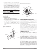
2. Remove and inspect sampling tube filters.
3. If filters are heavily coated with dirt, replace them with
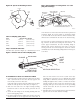
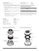
DETECTOR
HEAD
TEST COIL
H0292-00
Figure 9. RTS451/RTS451KEY test coil installation:
new filters. If they are not heavily coated, use a vacuum
cleaner or compressed air nozzle to remove dust, then
reinstall the filters.
4. Remove detector from housing. (See Figure 8.)
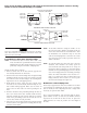
Photo Units
5. Remove detector cover by inserting a small blade screw-
driver into the slot located 90 degrees from the MOD400
test jack receptacle, twisting the cover counterclockwise
to remove (see Figure 10).
6. Lift screen from photo chamber. Vacuum screen and
cover before using clean, compressed air to loosen and
blow out any remaining debris. (Replacement screens
are available, part no. RS24.)
7. Vacuum photo chamber, then use clean compressed air
to blow area clean.
8. Replace screen by aligning arrow on top with the field
test slot on the base of the detector. Push screen into
place. Screen should fit tightly to chamber.
Ionization Units
9. Remove the detector cover and screen assembly by
depressing the three lock prongs on the top of the cover
and rotating the cover counterclockwise. The CRT400
Cover Removal Tool makes cover removal easier. (See
Figure 11.)
10. Carefully pull the screen out of the cover.
11. Clean the screen thoroughly with a soft brush or vacu-
um (replacement screen available, part no. RS14).
12. Brush or vacuum the inside of the cover. Cover may
then be blown out using clean, compressed air. DO
NOT APPLY WATER TO THIS AREA.
13. Vacuum the sensing chamber before using clean,
compressed air to loosen and blow out any remaining
debris. DO NOT APPLY WATER TO THIS AREA.
14. Press the screen back into the cover.
15. Replace the detector cover and screen assembly on
the sensing chamber. Rotate it clockwise to lock it into
place.