
Smoke Alarm User Manual
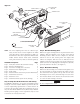

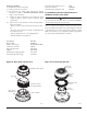


TWIST
COUNTERCLOCKWISE
TO REMOVE
DUCT
HOUSING
TWIST
CLOCKWISE
TO INSTALL
DETECTOR
HEAD
MOLDED RIB
TEST
MAGNET
PAINTED SIDE
TOWARD HOUSING
DUCT
DETECTOR
HOUSING
DETECTOR
HEAD
2. To determine that smoke is capable of entering the sens-
ing chamber, a visual examination should be conducted
to note any obscurations around the sensing chamber. If
a smoke test is required, smoke such as cigarette, cot-
ton wick, or punk smoke may be blown directly at the
smoke detector head. It is important to plug the exhaust
and sampling tube hole to prevent ducted air from blow-
ing smoke away from the smoke detector head. Record
all test records in the Detector Test Log (page 12).
CAUTION
Remember to remove the plugs after this test or the detec-
tor will not sense smoke in the air duct.
7.2 Alarm Tests
Before replacing the duct housing cover, the detector
interconnections should be checked. The DH500 may be
checked as follows:
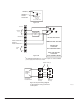
A. M02-04-00 Magnet Test
1. Make sure power is applied to the detector.
2. Place the painted surface of the test magnet against
the housing next to the rib molded onto the outside
of the housing (see Figure 7).
3. The LEDs on the detector should latch on as should
any accessories (i.e. RA400ZA, RTS451), and the
alarm condition should be verified at the control
panel.
Figure 7. Testing detector
H0275-00
D500-08-00 7 I56-512-07R
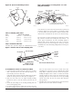
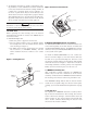
Figure 8. Detector head removal:
H0276-00
B. RTS451/RTS451KEY Remote Test Station
The RTS451/RTS451KEY Remote Test Station facilitates test
of the alarm capability of the duct detector as indicated in
the RTS451/RTS451KEY manual. The DH500 duct detector
cannot be reset by the RTS451/RTS451KEY. It must be reset
at the system control panel.
To install the RTS451/RTS451KEY test coil, connect the
device as shown in Figure 9; wire runs must be limited to
25 ohms or less per interconnecting wire. Place the coil in
the detector housing with the arrow facing up and pointing
toward the detector as in Figure 9. Attach the coil leads to
the housing terminals as shown; polarity is not important.
Firmly screw the bracket in place over the test coil.
7.3 MOD400 Sensitivity Test
After verification of alarm capability, the MOD400 test
module may be used with a voltmeter to check detector
sensitivity as indicated in the MOD400 installation manual.
The housing cover must be removed to perform this test.
If the MOD400 readings indicate that the detector head is
outside of the acceptable range, the detector head requires
cleaning. (See Periodic Maintenance Requirements on page
9.)
7.4 Trouble Test
The capability of “TROUBLE” detection is tested by remov-
ing the detector head from the duct housing. The detector
head is removed by turning it counterclockwise about 10
degrees (Figure 8). The system control panel should indi-
cate a trouble condition. Reinserting the detector head
should clear the trouble condition.