
Smoke Alarm User Manual

D100-67-00 6 I56-1148-04
SUPERVISORY
SWITCH
76
4
(+) IN (+) OUT
(+)
(+)
5
8
(–)
(–) IN (–) OUT
1ST DETECTOR
IN LOOP DH100
(–)
RA400Z (OPTIONAL)
REMOTE ALARM LED
2.8 VDC NOM.
IN ALARM
SUPERVISORY
SWITCH
76
4
(+) IN (+) OUT
(+)
(+)
5
8
(–)
(–) IN (–) OUT
LAST DETECTOR
IN LOOP DH100
(–)
RA400Z (OPTIONAL)
REMOTE ALARM LED
2.8 VDC NOM.
IN ALARM
E
O
L
R
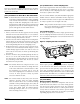
STYLE D OPTIONAL WIRING
UL LISTED
COMPATIBLE 2-WIRE
CONTROL PANEL
ALARM
INITIATION
LOOP
(+)
(–)
EOL RESISTOR
SPECIFIED BY
PANEL MANUFACTURER
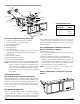
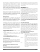
CAUTION
Do not loop wire under terminals when wiring detectors. Break wire runs to provide system supervision of connections.
1
2
3
4
5
6
7
3
4
5
Test +
Test / Reset –
Reset +
Test
Reset
RA +
RA –
V Out +
V In +
8
7
8
V In / V Out –
V In +
V In / V Out –
DH100
RTS451 KEY
6
2
1
Alarm
LED
No Connection
+
–
Panel
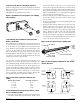
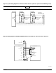
Figure 8. Wiring diagram for RTS451/RTS451KEY Remote Test Station to 2-wire duct smoke detectors:
A78-2350-00
Figure 7. System wiring diagram for 2-wire duct smoke detectors (detectors powered from initiating circuit):