
Smoke Alarm User Manual
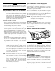

holes as indicated on the template. Insert the two jack nut
receptacles. Drive a #10 machine screw into the jacknut to
flare the retainer and then back the screw out to use for de-
tector mounting.
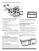
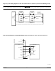
[5.2.1] Sampling Tube Installation for Ducts Less
Than 1
1
/2 Feet Wide (see Figure 2)
1. Remove the front cover.
2. Use the tube installation chart above to determine the
set screw setting.
3. Slide the sampling tube into the housing bushing.
4. Align the holes in the bushing with the holes in the sam-
pling tube. Make sure the number of holes exposed on
the supplemental tube matches the number as deter-
mined in step 2. Secure with the #8 self-tapping screw
into the bottom hole of the permanent tube.
NOTE: For ducts greater than 1
1
/2 feet in width, refer to
sections [5.4.1] and [5.4.2].
Figure 2. Sampling tubes connected to duct smoke
detector:
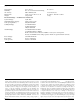
[4] Contents Of The Duct Smoke Detector Kit
1. Complete housing base and cover assembly
2. Two #10 machine screws for mounting
3. Two sampling tube filters
4. One test magnet
5. Drilling template
6. Two foam gaskets
7. Four #6-self tapping mounting screws for the metal
sampling tube and optional exhaust tube extension
8. Two jack nuts
9. One inlet tube end plug
10. Metal sampling tube end plug
11. One telescoping sampling tube
12. One #8 self-tapping screw for the telescoping sampling tube
NOTE: For ducts over 1
1
/2 feet, longer inlet sampling tubes
must be ordered to complete the installation. They
must be the correct length for the width of the duct
where they will be installed. See Table 1 on page 3
to determine the inlet tube required for different
duct widths.
[5] Installation Sequence
[5.1] Verify Duct Air Flow Direction And Velocity
Model DH100 detectors are designed to be used in air han-
dling systems having air velocities of 500 to 4000 feet per
minute. Be sure to check engineering specifications to en-
sure that the air velocity in the duct falls within these pa-
rameters. If necessary, use a velocity meter to check the air
velocity in the duct.
[5.2] Drill The Mounting Holes
Remove the paper backing from the mounting template
supplied. Affix the template to the duct at the desired
mounting location. Make sure the template lies flat and
smooth on the duct. Center punch holes A and B. Drill the
D100-67-00 2 I56-1148-04
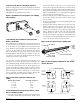
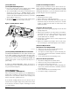
[3] Figure 1: Exploded View Of Duct Detector Components
FOAM
GASKETS
TELESCOPING TUBE
CONDUIT HOLES
DETECTOR
HOUSING
TERMINAL STRIP
DETECTOR
COVER
SAMPLING TUBE
FILTERS
COVER MOUNTING
SCREWS
TELESCOPING TUBE
#8 SELF-TAPPING SCREW
POWER BOARD
DETECTOR BOARD
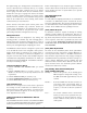
Tube Installation Chart:
Supplemental Duct
Tube Holes Width
512″-14″
614″-16″
716″-18″