
User manual


D550-06-00 3 I56-1367-004R
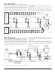
Figure 4. Wiring diagram:
Detector Activates Sounder Base(s) - (Complies with UL268)
UL has approved grouping for up to six B501BHT base with
horn units. When wired as a group, any detector in the group
that has its LED’s latched on by the panel will cause other
B501BHT units in the group to sound. This type of “local”
grouping is accomplished by wiring the grouped devices to-
INTELLIGENT
MONITOR
MODULE
(+) 2
(–)
1
67
U.L.
LISTED
EOL
RESISTOR
47K
U.L.
LISTED
EOL
RELAY
24V
5
4
123
5
4
123
5
4
123
(+) COMM.
(–) COMM.
(–) POWER
(+) POWER
U.L. LISTED COMPATIBLE
CONTROL PANEL
EXTERNAL
24V SUPPLY
CLASS A OPTIONAL WIRING
CLASS A OPTIONAL WIRING
*
GROUPING OF UP TO 6 MODEL B501BHT TEMPORAL TONE SOUNDER BASES.
OPTIONAL SOUNDER INTERCONNECT
*
gether using terminal 5, Sounder Base Interconnect, as shown
in the diagram.
NOTE: Since a local grouping of horns is not supervised, the
groups can only be used as a supplementary evacuation system.
It is not acceptable to group horns for primary alarm signaling.
C0474-00
UL LISTED
COMPATIBLE
CONTROL
PA NEL
INTELLIGENT
MONITOR
MODULE
INTELLIGENT
RELAY
MODULE
FIRST
SOUNDER
BASE
(+) POWER
(–) POWER
LAST
SOUNDER
BASE
(–) COMM.
(+) COMM.
UL
LISTED
EOL
RELAY
24V
UL LISTED
EOL
RESISTOR
47k
UL LISTED
24V SUPPLY
SLC
(+)
(–)
THIS IS A STANDARD RELAY
MODULE CONFIGURED TO
REVERSE THE POWER
OPTIONAL SOUNDER INTERCONNECT
*
*
GROUPING OF UP TO 6 MODEL B501BHT TEMPORAL TONE SOUNDER BASES.
†
†
Figure 5. Wiring diagram:
Detector Activates Sounder Base(s); Intelligent Relay Module Ac-
tivates All Sounder Bases - (Complies with UL 268 and UL 464)
UL has approved grouping of up to six B501BHT bases with
horn units. When wired as a group, any detector in the group
that has its LED’s latched on by the panel will cause other
B501BHT units in the group to sound. This type of “local”
C0968-00
grouping is accomplished by wiring the grouped devices to-
gether using terminal 5, Sounder Base Interconnect, as shown
in the diagram.
NOTE: Since a local grouping of horns is not supervised, the
groups can only be used as a supplementary evacuation sys-
tem. It is not acceptable to group horns for primary alarm
signaling.