
User manual


D550-06-00 2 I56-1367-004R
For signal wiring (the wiring between interconnected sensors
or modules), it is recommended that the wire be no smaller
than 18 gauge (1.0 square mm). Wire sizes up to 12 gauge (2.5
square mm) may be used with the base. For best system per-
formance, the power (+ and –) wires and the communication
circuit wires should be twisted pair or shielded cable installed
in separate grounded conduit to protect the communication
loop from electrical interference.
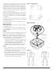
Make wire connections by stripping about
3
⁄8” of insulation
from the end of the wire. Then, slide the bare end of the
wire under the clamping plate, and tighten the clamping
plate screw. Do NOT loop the wire under the clamping plate
(See Figure 3).
The zone wiring of the sensor base should be checked before
the sensor heads are installed. Check the wiring for continuity
and polarity in the base.
See the individual sensor manual for the maximum sensor in-
stallation temperature.
Wiring Instructions
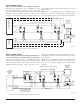
NOTE: External supply shown in normal standby configura-
tion in Figure 4 and 5.
The wiring diagram for a typical 2-wire intelligent system is
shown in Figure 4 and 5 (the monitor module is supervising
the external supply).
Testing
Sensors and bases must be tested after installation and as an inte-
gral part of periodic maintenance. Test the B501BHT as follows:
NOTE: Before testing, notify the proper authorities that the
smoke sensor system is undergoing maintenance and, there-
fore, will be temporarily out of service. Disable the system un-
dergoing maintenance to prevent unwanted alarms.
1. If configured as in Figure 4 or 5, reverse the polarity of the
external 24VDC supply. If configured as in Figure 5, turn
on the Intelligent Relay Module. All B501BHT bases on the
loop should sound in approximately 10 seconds.
2. Latch the sensor LED on from the control panel. That unit’s
B501BHT should sound in approximately 10 seconds.
NOTES:
1. There is approximately a 10 second delay built into the
B501BHT before sounding. This delay is present whether
the control signal comes from the sensor or from the exter-
nal power supply polarity being reversed.
2. During automatic testing cycles, the horn may sound if
the associated sensor is left in the test mode with LEDs
latched on for more than 4 seconds. Therefore, it is neces-
sary to complete testing of each sensor within this 4-sec-
ond limit to prevent the horn from sounding.
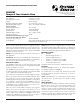
Figure 1. Terminal layout:
Figure 2. Mounting:
MOUNT B501BHT
TO ELECTRICAL BOX
4 INCH SQUARE BOX
Figure 3:
C0471-00
C0472-00
C0473-00