
Smoke Alarm User Manual

6
Note: This document is based on the recommendations of BS5839 Part 1: 2002. It is intended only as a guide to the application of fire detection systems.
Reference must be made to relevant national and local standards.
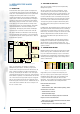
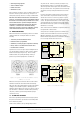
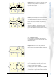
1.6. DRIFT COMPENSATION AND MAINTENANCE ALARM
The sensitivity of a smoke detector tends to change as it
becomes contaminated with dirt or dust (see figure 1.6.1). As
contamination builds up, it usually becomes more sensitive,
leading to the risk of a false alarm, but in some cases can
become less sensitive, so delaying the alarm if a fire is
detected. To counter this, if a detector drifts outside its
specification, a maintenance signal may be sent to the panel
warning that the detector needs cleaning.
To further increase the maintenance interval, many systems
incorporate a “drift compensation” function, included in either
the detector or the control panel algorithms. These functions
use algorithms that monitor the sensitivity of a detector, and
modify its response to compensate for a build up of dust in
the chamber over time. Once the detector reaches the “drift
limit” when the dirt build up can no longer be compensated
for, a fault can be signalled. Some systems also incorporate
a warning to signal that a detector is approaching its
compensation limit and requires cleaning.
Figure 1.6.1 Chamber Contamination and Drift
Compensation
1.7. PRE-ALARM FACILITY
One advantage of intelligent type systems is that since the
data sent by a detector to the panel varies with the local
environment, it can be used to detect when the device is
approaching an alarm condition. This “Pre-Alarm” can be
signalled at the panel and can therefore be investigated to
check if there is a real fire, or if it is caused by other signals,
for example steam or dust from building work. This can
avoid the inconvenience and expense of evacuating a building
or calling out the fire brigade unnecessarily because of a
nuisance alarm. The Pre-Alarm Threshold is typically set at
80% of the alarm threshold.
1.8. FIRE ALARMS
When a fire is detected, the control panel indicates an alarm
by activating the fire indicator for the relevant zone on the
control panel, sending a command to the relevant detector
to illuminate its LED and activate alarm signals to start
evacuation. Most intelligent fire system control panels include
alphanumeric displays enabling them to show information
on the source of the alarm. This may simply be a zone and
detector address, or could be more descriptive for example
“Smoke Detector, Bedroom 234”. The control panel may also
use control modules to operate additional electrical equipment
such as air conditioning units and door releases to prevent the
spread of smoke and fire.
The alarm signals can either be a zone of conventional
sounders and strobes activated via control modules on the
loop or directly from the control panel, or addressable loop
powered devices connected on the same loop as the detectors
and activated by direct command from the panel. Loop
powered sounders tend to have lower wiring costs, however
the number permissible on the loop may be restricted by
current limitations.
On larger sites, it may be desirable to use zoned alarms. This
allows a phased evacuation to be carried out, with areas
at most immediate risk being evacuated first, then less
endangered areas later.
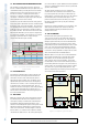
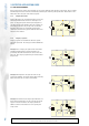
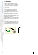
1.9. FIRE SYSTEM ZONES
Conventional fire alarm systems group detectors into
‘zones’ for faster location of a fire, with all the detectors in
a particular zone being connected on one circuit. Although
intelligent systems allow the precise device that initiated an
alarm to be identified, zones are still used in order to make
programming the system and interpreting the location of a fire
easier. The control panel will have individual fire indicators
for each zone on the system, and the control panel response
to an alarm is often programmed according to the zone of the
device in alarm rather than its individual address.
Whilst the division of a loop into zones is achieved within the
panel software, BS5839 part 1 recommends that a single
wiring fault in one zone should not affect the operation
of the system in other zones of the building. To meet this
recommendation, a short circuit isolator should be placed on
each boundary between zones (figure 1.9.1). In this instance,
a short circuit in one zone would cause the isolators on either
side of the zone to open, thereby disabling that zone. Any
devices in neighbouring zones would be protected by the short
circuit isolators and remain operational.
Figure 1.9.1 Intelligent System Fire Zones
Intelligent Fire Alarm Systems
Chamber
Value
Time
Clean Air
Value
Uncompensated
Alarm Threshold
Uncompensated
Chamber
Value
Compensated
Threshold
Smoke required to
reach alar
m
threshold reduces
-
Detector sensitivity
increases
Threshold
increased to
compensate for
increased chamber
clean air value.
ISOLATOR
ISOLATO
R
ISOLATOR
Zone 1
Zone 2
Zone
3
Zone 4
INTELLIGENT
FIRE ALARM
CONTROL
PANEL
FIRE ALARM SYSTEM OK
28
January 2003
12:15 pm
SYSTEM OK
SYSTEM RESET
FIRE ALARM
FAULT