
User guide

D400-08-00 3 I56-280-05R
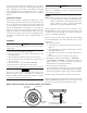
Wire connections are made by stripping about
3
⁄8″ of insu-
lation from the end of the wire (use strip gauge molded in
base), sliding the bare end of the wire under the clamping
plate, and tightening the clamping plate screw. A typical
wiring diagram for a 4-wire detector system is shown in
Figure 3.
Tamper-proof Feature
This detector includes a tamper-proof feature that, when
activated, prevents removal of the detector without the use
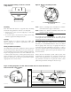
of a tool. To activate this feature, break off the smaller tab
at the scribed line on the tamper-proof tab, located on the
detector mounting bracket (see Figure 2), then install the
detector. To remove the detector from the bracket once the
tamper-proof feature has been activated, depress the tam-
per-proof tab located in the slot on the mounting bracket
(see Figure 4) and turn the detector counterclockwise for
removal.
Installation
WARNING
Remove power from initiating-device circuits before install-
ing detectors.
1. Wire detector per installation guidelines.
2. Line up arrows on the detector with arrows on the
mounting bracket.
3. Turn the detector clockwise until it clicks into place.
4. After all detectors have been installed, apply power to
the control unit.
5. Test the detector as described under TESTING.
6. Reset the detector at the system control panel.
7. Notify the proper authorities the system is in operation.
CAUTION
Dust covers can be used to help limit dust entry to the
detector, but they are not a substitute for removing the
detector during building construction. Remove any dust
covers before placing system in service.
CAUTION
Smoke detectors are not to be used with detector guards
unless the combination has been evaluated and found
suitable for that purpose.
Testing
NOTE: Before testing, notify the proper authorities that
the smoke detector system is undergoing main-
tenance, and therefore will temporarily be out of
service. Disable the zone or system undergoing
maintenance to prevent unwanted alarms.
Before testing the detector, look for the presence of the
flashing LED. If it does not flash, power has been lost to
the detector (check the wiring), or it is defective (return for
repair, see warranty information).
Detectors must be tested after installation and following
periodic maintenance. The 1412 and 1424 may be tested
as follows:
A. Recessed Test Switch
1. A test switch is located on the detector housing (see
Figure 4).
2. Push and hold the recessed test switch with a 0.1 inch
maximum diameter tool.
3. The LED on the detector should light within 30 sec-
onds.
4. Reset the detector at the system control panel.
B. Test Module (System Sensor Model No. MOD400R)
The MOD400 or MOD400R is used with an analog or
digital voltmeter to check the detector sensitivity as
described in the test module’s manual.
C. Aerosol Generator (Gemini 501)
Set the generator to represent 4%/ft. to 5%/ft. obscura-
tion as described in the Gemini 501 manual. Using the
bowl shaped applicator, apply aerosol until unit alarms.
Notify the proper authorities the system is back on line.
Detectors that fail these tests should be cleaned as described
under MAINTENANCE and retested. If the detectors still
fail these tests, they should be returned for repair.
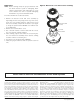
PUSH RECESSED TEST SWITCH WITH
A 0.1" MAX. DIAMETER TOOL.
TEST MODULE
SOCKET
LED
RECESSED
TEST SWITCH
TAMPER SLOT
Figure 4. Bottom and side view showing position of test switch:
S0142-00