
User guide

D400-08-00 2 I56-280-05R
Mounting
Each 1412 and 1424 detector is supplied with a mounting
bracket kit that permits the detector to be mounted:
1. Directly to a 3
1
⁄2 inch or 4 inch octagonal, 1
1
⁄2 inch deep
electrical box, or
2. To a 4 inch square electrical box by using a plaster ring
with the supplied mounting bracket kit.
Spacing
Spacing of 30 ft. on a smooth ceiling as per NFPA 72E.
Where conditions or response requirements vary, other
spacing may apply.
Wiring Installation Guidelines
All wiring must be installed in compliance with the National
Electrical Code and the applicable local codes, and any spe-
cial requirements of the local authority having jurisdiction.
Proper wire gauges should be used. The conductors used
to connect smoke detectors to control panels and accessory
devices should be color-coded to prevent wiring mistakes.
Improper connections can prevent a system from respond-
ing properly in the event of a fire.
NOTE: Refer to releasing device manufacturer’s installa-
tion instruction for proper connections.
NOTE: Contacts are shown in stand-by mode and will
transfer in alarm condition.
CAUTION
For system supervision: for terminals 1, 2, 7, and 8, do not
use looped wire under terminals. Break wire run to provide
system supervision of connections.
For signal wiring (the wiring between interconnected
detectors), it is recommended that the wire be no smaller
than 18 gauge. Wire sizes up to 12 gauge wire may be
used. For best system performance, the power (+) and (–)
loop wires should be twisted pair and installed in separate
grounded conduit to protect the loop from extraneous elec-
trical interference.
Smoke detectors and alarm system control panels have
specifications for allowable loop resistance. Consult the
control panel manufacturer’s specifications for the total
loop resistance allowed for the particular model control
panel being used before wiring the detector loops.
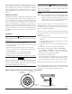
TAMPER
RESISTANT
TAB
TO
MAKE DETECTOR TAMPER RESISTANT,
BREAK OFF TAB EXTENSION
AT
SCRIBED LINE
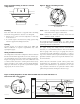
Figure 1. Flush mounting of detector on 4 inch
octagonal box:
Figure 2. Detector mounting bracket:
S0139-00
S0140-00
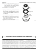
COMMON
N/O
N/C
AUXILIARY
CONTACTS
FORM C
4
5
6
7
8
2
1
+
-
POWER
ALARM
CONTACTS
FORM A
N/O
A78-1811-00
S0165-00
Figure 3. Wiring diagram for models 1412 and 1424 detectors used with Class A or
Class B four-wire control panels.