
Instruction Manual

SS-400-001 1 I56-3858-004R
1251B Plug-in Intelligent
Ionization Sensor with Communications
INSTALLATION AND MAINTENANCE INSTRUCTIONS
3825 Ohio Avenue, St. Charles, Illinois 60174
1-800-SENSOR2, FAX: 630-377-6495
www.systemsensor.com
BEFORE INSTALLING
This sensor must be installed in compliance with the control panel system
installation manual. The installation must meet the requirements of the Au-
thority Having Jurisdiction (AHJ). Sensors offer maximum performance when
installed in compliance with the National Fire Protection Association (NFPA);
see NFPA 72.
GENERAL DESCRIPTION
Model 1251B intelligent ionization sensor uses a state-of-the-art sensing cham-
ber. These sensors are designed to provide open area protection and are in-
tended for use with compatible control panels only.
Two LEDs on each sensor light to provide a local, visible sensor indication.
Remote LED annunciator capability is also available as an optional accessory
(RA400Z/RA100Z).
The 1251B requires compatible addressable communications to function
properly. Connect this sensor to listed-compatible control panels only.
SPACING
System Sensor recommends spacing sensors in compliance with NFPA 72. In
low air flow applications with smooth ceilings, space sensors 30 feet apart.
For specific information regarding sensor spacing, placement, and special ap-
plications, refer to NFPA 72 or the System Smoke Detector Application Guide,
available from System Sensor.
WIRING GUIDE
All wiring must be installed in compliance with the National Electrical Code,
applicable local codes, and any special requirements of the Authority Having
Jurisdiction. Proper wire gauges should be used. The installation wires should
be color-coded to limit wiring mistakes and ease system troubleshooting. Im-
proper connections will prevent a system from responding properly in the
event of a fire.
Remove power from the communication line before installing sensors.
1. Wire the sensor base (supplied separately) per the wiring diagram, see
Figure 1.
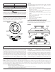
2. Set the desired address on the sensor address switches, see Figure 2.
3. Install the sensor into the sensor base. Push the sensor into the base
while turning it clockwise to secure it in place.
4. After all sensors have been installed, apply power to the control unit and
activate the communication line.
5. Test the sensor(s) as described in the TESTING section of this manual.
CAUTION
Dust covers provide limited protection against airborne dust particles during
shipping. Dust covers must be removed before the sensors can sense smoke.
Remove sensors prior to heavy remodeling or construction.
SPECIFICATIONS
Operating Voltage Range: 15 to 32 VDC
Maximum Average Standby Current: 300µA @ 24 VDC (one communication every 5 seconds with LED blink enabled)
Maximum Alarm Current (LED on): 6.5 mA @ 24 VDC
Operating Humidity Range: 10% to 93% Relative Humidity, Non-condensing
Operating Temperature Range: 32°F to 120°F (0°C to 49°C)
Height: 2.0˝ (51 mm) installed in B210LP Base
Diameter: 6.1˝ (155 mm) installed in B210LP Base; 4.1˝ (104 mm) installed in B501 Base
Weight: 5.4 oz. (153 g)
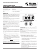
FIGURE 1. WIRING DIAGRAM:
2
3
1
2
3
3
1
2
1
(–)
(+)
+-
UL LISTED COMPATIBLE
CONTROL PANEL
CAUTION: DO NOT LOOP WIRE
UNDER TERMINAL 1 OR 2.
BREAK WIRE RUN TO PROVIDE
SUPERVISION OF CONNECTIONS.
CLASS A OPTIONAL WIRING
REMOTE
ANNUNCIATOR
(–)
(+)
C0129-02
FIGURE 2. ROTARY DECADE ADDRESS SWITCHES:
TENS ONES
9
8
7
6
5
4
3
2
1
0
9
8
7
6
5
4
3
2
1
0
C0146-00
TAMPER-RESISTANCE
Model 1251B includes a tamper-resistant capability that prevents their re-
moval from the bracket without the use of a tool. Refer to the base manual for
details on making use of this capability.
TESTING
Before testing, notify the proper authorities that the system is undergoing
maintenance, and will temporarily be out of service. Disable the system to
prevent unwanted alarms.
All sensors must be tested after installation and periodically thereafter. Testing
methods must satisfy the Authority Having Jurisdiction (AHJ). Sensors offer max-
imum performance when tested and maintained in compliance with NFPA 72.
Test the sensors as follows:
A. Functional: Magnet Test (P/N M02-04-01 or M02-09-00)
This sensor can be functionally tested with a test magnet. The test mag-
net electronically simulates smoke in the sensing chamber, testing the
sensor electronics and connections to the control panel.
1. Hold the test magnet in the magnet test area as shown in Figure 3.
2. The sensor should alarm the panel.
Two LEDs on the sensor are controlled by the panel to indicate sensor
status. Coded signals, transmitted from the panel, can cause the LEDs
to blink, latch on, or latch off. Refer to the control panel technical docu-
mentation for sensor LED status operation and expected delay to alarm.
B. Smoke Entry
The GEMINI model 501 aerosol generator can be used for smoke entry
testing. Set the generator to represent 4%/ft to 5%/ft obscuration as de-
scribed in the GEMINI 501 manual. Using the bowl shaped applicator,
apply aerosol until the panel alarms.
Additionally, canned aerosol simulated smoke (canned smoke agent)
may be used for smoke entry testing of the smoke detector. Tested and
approved aerosol smoke products are:
I56-3858-004R