
User's Manual
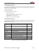
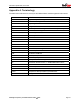
Table Of Contents
- Scope
- Product Overview
- Functional and Electrical Requirements
- Electromagnetic Compatibility
- Mechanical Requirements

V3d Product Specification, Version 2.06
5.3 External Connectors
Five connectors are required, four for RF and one for sensors, serial and power. All connectors
are mounted in the same facing of the enclosure, which is normally facing downward when
installed. All pins are ESD protected.
5.3.1 RF Connectors
The three RF connectors are as follows:
a) GPS: SMA Jack female
b) GSM Cellular: SMA Jack, with Reverse Polarity
c) ORBCOMM VHF: TNC Jack female
d) ZigBee: TNC Jack, with Reverse Polarity
5.3.2 Power I/O Connector
The serial, digital and analog I/O and power are combined into a single positive lock marine-
grade connector. The connector shall be keyed to prevent incorrect pin to socket mating. The
pin designations are as follows:
Interface Description Pin Count
Li-ion Charging
Power
For connection to external Li-ion charger 1
SLA Charging
Power
For connection to external SLA charger 1
External Power Enables powering the device externally 1
Charging Ground Ground for external charger, external power 1
Main Serial RS232 TX, RX, GND 3
MCU Serial RS232 TX, RX (for reprogramming only) 2
Door Sense & Gnd Routed to external door sensor 2
Analog In General purpose 10-bit 1
Digital In For sensing external charger activity 1
Power Out Available 3.3V, low current 1
Analog Gnd For low-noise analog reads 1
Total:
15
Figure 1: Power I/O Connector Designations
MobiApps Proprietary & Confidential Document
©
2006 Page 19