
User's Manual
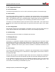
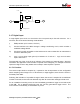
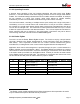
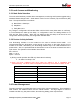
Table Of Contents
- Scope
- Product Overview
- Functional and Electrical Requirements
- Electromagnetic Compatibility
- Mechanical Requirements

V3d Product Specification, Version 2.06
+ 3.3V
DNA
0 Ω
3.1.7 Digital Input
A single digital input circuit is to be wired to the front panel 20-pin Conxall connector. As a
minimum, the circuit has the following characteristics:
i) ESD protection (8 kV contact, 15 kV air)
ii) Circuits interface to the MCU through a voltage conditioning circuit, which includes a
modifiable voltage divider.
iii) Circuits to be easily accessible on the SAS board in order to allow SPC to customize the
circuits for different inputs.
iv) Logic 1 occurs when input (point A) is between 2.5 V and 16 V. Logic 0 occurs when
input is below 2.5 V.
The expected use of the circuit is as an indicator of the presence of external power. With this
information the application would be able to operate more intelligently, for example to transmit
reports at a higher rate or stay awake and not sleep if external power is present.
3.1.7.1 Function
The sensor output shall be sampled by / reported to the microprocessor at the configurable
sensor sampling rate of range from 1 to 60 seconds, or edge triggered, even when the V3d is in
its lowest power state.
Following first indication of a possible change of state, the sensor is sampled for an additional
number of seconds, and an event is declared only after all consecutive readings indicate such.
For an unattached mounting event, the V3d immediately generates a logger record and sends
to the IMB. For an attached mounting event, the V3d only generates a logger record. The
mount sensor is immediately re-armed after any event.
0 Ω
DNA
0 Ω
B
A
Analog Ground
MobiApps Proprietary & Confidential Document
©
2006 Page 9