SPC GlobalTrak Product Specification Written by: MobiApps Inc. 7315 Wisconsin Ave, Suite 1050 E Bethesda, MD 20814 System Planning Corporation 1000 Wilson Blvd. Arlington, VA 22201 This document contains confidential and proprietary information of SPC and MobiApps. Disclosure to unauthorized third parties without the expressed, written permission of MobiApps Inc. is prohibited. Version: 2.
V3d Product Specification, Version 2.
V3d Product Specification, Version 2.06 Confidentiality Notice This document contains technical information propriety to MobiApps, Inc. Any and all information contained herein is of a confidential nature, and may only be reviewed by MobiApps employees or authorized personnel.
V3d Product Specification, Version 2.06 Revision History Version # Date Description of Changes Author 2.02 20-Aug-06 Shift from V3c/p to V3d. Numerous Changes, all tracked in MS Word. 2.03 28-Aug-06 Added revisions following internal review 2.05 30-Aug-06 Added revisions following SPC review 2.06 14-Sep-06 Added revisions following CDR 2.07 15-Sep-06 More revision following CDR R. Straz 2.10 14-Nov-07 Added Always on Mode R. Straz S.
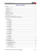
V3d Product Specification, Version 2.06 Table of Contents 1.0 SCOPE.................................................................................................................................................... 1 1.1 PURPOSE AND OVERVIEW ....................................................................................................................................1 1.2 AUDIENCE .........................................................................................................................
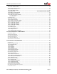
V3d Product Specification, Version 2.06 3.3.1 Main Serial Interface ..................................................................................................................... 13 3.3.2 Device Activity Indicator................................................................................................................ 13 3.4 POWER MANAGEMENT .......................................................................................................................................13 3.4.
V3d Product Specification, Version 2.06 APPENDIX A. TERMINOLOGY......................................................................................................................... A-1 APPENDIX B. V3D REQUIREMENTS TRACEABILITY MATRIX ..............................................................B-2 APPENDIX C. V3D DATA SHEET .....................................................................................................................
V3d Product Specification, Version 2.06 1.0 Scope 1.1 Purpose and Overview This document provides a complete product specification for the V3d and in part its predecessor the V3c. All application-level environmental, mechanical, electrical and functional requirements are specified, sufficient to enable development and subsequent design verification of the V3d product.
V3d Product Specification, Version 2.06 Optional Priority [OP] – not required, but worth listing in the product specification should the selected design architecture enable inclusion at no cost. Negotiable Priority [NP] – the requirement is not firm and may be modified to an alternative requirement based on trade-offs in cost, performance or desirability of feature. Future Priority [FP] – can be added in a successive generation.
V3d Product Specification, Version 2.06 1.8 References The following documents are referenced in this product specification: • European Telecommunications Standards Institute, EN 300 832 (A1 version 1.1.1), Electromagnetic Compatibility for Mobile Earth Stations, 2003. • International Electrotechnical Commission, IEC 61000-4-6, Testing and Measurement Techniques — Immunity to Conducted Disturbances, Induced by Radio-Frequency Fields, Second Edition, May 2003.
V3d Product Specification, Version 2.06 2.0 Product Overview The GlobalTrak V3d enables location tracking and monitoring of containers in near real-time over GSM and ORBCOMM. The V3d uses a magnetic door switch to constantly monitor the door's status. When the door is opened, the junction in the magnetic relay is broken and an alarm is immediately sent to the Information Management Bureau (IMB). Along with door open alarms, the V3d sends periodic location reports using its internal GPS module.
V3d Product Specification, Version 2.06 3.0 Functional and Electrical Requirements This section details the general functional and electrical requirements of the V3d, including the higher-level application functions, sensor response and GPS. 3.1 Sensors 3.1.1 Optic Sensor 3.1.1.1 Performance The sensor spectral response wavelength range shall be from 320 to 840 nm λ, with sensitivity greater than 0.3 A/W across the range. 3.1.1.
V3d Product Specification, Version 2.06 a logger record is to be immediately generated and sent to the IMB. The measured value is a peak of the sensor output over the previous interval. The sensor is re-armed after the sensor level returns from the alarm state. At the point where the sensor level crosses the threshold back to a typical level the sensor alarm is once again active. 3.1.2.3 Configuration The threshold shall be user programmable, changeable over-the-air through either network or locally.
V3d Product Specification, Version 2.06 3.1.4 Temperature Sensor 3.1.4.1 Performance The sensor range shall be from -40°C to +85°C, with accuracy within 2°C across this range. 3.1.4.2 Function The sensor output shall be sampled by / reported to the microprocessor at the configurable sensor sampling rate of range from 1 to 60 seconds, even when the V3d is in its lowest power state.
V3d Product Specification, Version 2.06 3.1.5.3 Configuration The minimum number of consecutive readings shall be user programmable, changeable overthe-air through either network or locally. Also the consecutive threshold can be disabled, such that no event message is generated. 3.1.5.
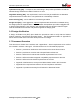
V3d Product Specification, Version 2.06 + 3.3V DNA A 0Ω 0Ω 0Ω B DNA Analog Ground 3.1.7 Digital Input A single digital input circuit is to be wired to the front panel 20-pin Conxall connector. As a minimum, the circuit has the following characteristics: i) ESD protection (8 kV contact, 15 kV air) ii) Circuits interface to the MCU through a voltage conditioning circuit, which includes a modifiable voltage divider.
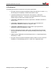
V3d Product Specification, Version 2.06 3.1.7.2 Configuration The minimum number of consecutive readings shall be user programmable, changeable overthe-air through either network or locally. Also the consecutive threshold can be disabled, such that no event message is generated. The circuit enables customization of the inputs to adapt to varying sensors. The basic diagram is shown below. Rectangular blocks represent spaces where SMT 1/8W resistors can be placed (possibly 0 ohm).
V3d Product Specification, Version 2.06 3.2.2 ORBCOMM Satellite System The ORBCOMM system is a two-way system that supports communication to and from mobile or fixed Subscriber Communicators (SCs). In most applications, a message or other data is first generated by an SC. From that source, the data is transmitted to the nearest ORBCOMM satellite. The satellite downlinks the data to the selected Gateway Earth Station (GES), which then transmits the data to the desired Gateway Control Center (GCC).
V3d Product Specification, Version 2.06 3.2.3.3 Operating Scenario A planned future capability of the V3d includes networking with other V3d’s using ZigBee protocols1. Local star networks inside each shipping container connect to a large mesh network outside. The coordinators assign themselves when an outside network is available, for example the top container in a stack.
V3d Product Specification, Version 2.06 3.3 Local Access and Monitoring 3.3.1 Main Serial Interface The main serial interface provides device management, monitoring and firmware upgrade using standard RS232 voltage levels. Serial data is carried on the Transmit (TX) and Receive (RX) lines.
V3d Product Specification, Version 2.06 3.4.1 Main Battery Switch A method is to be provided which enables complete disconnection of the internal batteries from the electronics, to preserve shelf life and minimize battery recharging / replacement events. The method shall be clandestine or keyed to reduce the opportunity for deviant or accidental behavior resulting in deactivation of the V3d. 3.4.
V3d Product Specification, Version 2.06 3.5 GPS Receiver 3.5.1 Time to First Fix The GPS receiver shall take no longer than 45 seconds (95%) to get a position fix from a warm start (i.e., almanac loaded and more than two hours since the last fix) and no longer than 15 seconds (95%) from a hot start (i.e., less than two hours since the last fix). 3.5.
V3d Product Specification, Version 2.06 • Lithium Thionyl Chloride, assembled from three 3.6V cells providing a nominal voltage of 10.8V. This is primary battery which cannot be recharged. • Lithium Ion, assembled from three 3.6V cells providing a nominal voltage of 10.8V. This is a rechargeable battery; however charging is possible over a limited temperature range compared to discharging. • Sealed Lead Acid, assembled from five 2V cells, providing a nominal voltage of 10V.
V3d Product Specification, Version 2.06 4.0 Electromagnetic Compatibility The relevant electromagnetic compatibility requirements for the intended product use are detailed below. Note: All requirements in this section are expected to be met by the V3d product, based on component ratings and product design, but will not be verified in the DVT. 4.
V3d Product Specification, Version 2.06 5.0 Mechanical Requirements The relevant mechanical requirements for the intended product use are detailed below. 5.1 Lifespan All mechanical components (RF shielding and packaging) shall have an expected availability of a minimum of 3 years. 5.2 Physical Parameters 5.2.1 Enclosure Size The V3d enclosure shall have a maximum footprint of 18.5 x 22.1 cm (7.3” x 8.7”) and shall have a height of no more than 7.6 cm (3.0”). 5.2.
V3d Product Specification, Version 2.06 5.3 External Connectors Five connectors are required, four for RF and one for sensors, serial and power. All connectors are mounted in the same facing of the enclosure, which is normally facing downward when installed. All pins are ESD protected. 5.3.1 RF Connectors The three RF connectors are as follows: a) GPS: SMA Jack female b) GSM Cellular: SMA Jack, with Reverse Polarity c) ORBCOMM VHF: TNC Jack female d) ZigBee: TNC Jack, with Reverse Polarity 5.3.
V3d Product Specification, Version 2.06 5.3.3 Connector Mating Durability All connectors shall have a minimum 100 mating cycles rating. 5.3.4 Battery Pack Connector The battery pack connector is internal to the V3d enclosure. It connects the battery pack power and ground leads to the power input circuitry of the V3d, and to the internal Power I/O Connector harness (specifically, to the charging power and charging ground pins).
V3d Product Specification, Version 2.06 5.5 Power I/O Cable Assembly A cable assembly enables access to the Power I/O connector. Each battery charging lead is color coded 20 AWG and is terminated into a keyed shrouded power connector, accompanied by a ground wire. Similar for the external power lead. The main serial leads are color coded 24 AWG and are terminated into a 9-pin D-sub connector to enable simple connection to a PC.
V3d Product Specification, Version 2.06 Appendix A. Terminology The table below defines terms, acronyms and abbreviations used throughout this document.
V3d Product Specification, Version 2.06 Appendix B. V3d Requirements Traceability Matrix Specification Paragraph Compliance Remarks Statement 3.0 Functional and Electrical Requirements 3.1 Sensors 3.1.1 Optic Sensor 3.1.1.1 Performance 3.1.1.2 Function 3.1.1.3 Configuration 3.1.1.4 Mounting 3.1.2 Acoustic Sensor 3.1.2.1 Performance 3.1.2.2 Function 3.1.2.3 Configuration 3.1.2.4 Mounting 3.1.3 Door Sensor 3.1.3.1 Performance 3.1.3.2 Function 3.1.3.3 Configuration 3.1.3.4 Mounting 3.1.
V3d Product Specification, Version 2.06 3.2.3.3 Operating Scenario 3.2.3.4 Ember ZigBee 3.3 Local Access and Monitoring 3.3.1 Serial Interface 3.3.2 Device Activity Indicator 3.4 Power Management 3.4.1 Main Battery Switch 3.4.2 Battery Life 3.4.3 Wakeup from Sleep 3.4.4 Real-Time Clock 3.4.4.1 RTC Accuracy 3.4.4.2 Hour Meter 3.5 GPS Receiver 3.5.1 Time to First Fix 3.5.2 Position Accuracy 3.5.3 Antenna Connection Status 3.6 Data Storage and Logging 3.6.1 Log Storage Capacity 3.6.2 Log Storage Viewing 3.6.
V3d Product Specification, Version 2.06 5.4.2 Operating Temperature 5.4.3 Shock 5.4.4 Vibration 5.5 Power I/O Cable Assembly 5.6 Component Serial Designations 5.
V3d Product Specification, Version 2.06 Appendix C. V3d Data Sheet General Enclosure Dimension: 10.2 x 15.3 x 5.1 cm Configuration: Electronics & battery housed in sealed enclosure Transmit Frequency 148 to 150.