
User's Manual
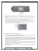
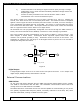
Table Of Contents
- 1.1 GT Lite Overview
- 2.1 GT Lite Detailed Hardware Description
- 2.2 GT Lite Detailed Software Description
- 3.1 Updating the Main Processor Software
- 3.2 Updating Main Processor Firmware
- 3.3 Programming the Low Power Controller
- 3.4 Recovering the GT Lite
- 4.1 Install GT Lite USB Drivers
- 4.2 Create HyperTerminal Connection
- 4.3 Connect GT Lite to HyperTerminal
- 5.1 Monitoring the GT Lite
- Diagnostic Overview
- Common GT Lite Functions
- Common Diagnostic Output
- APPLICATION: IMEI:
- APPLICATION: Firmware Version:
- APPLICATION: (batteryVoltageCallback) millivolts=4101, mAh =
- APPLICATION: (messageCallback) ZIGBEE_STAR_AWAKE
- APPLICATION: (messageCallback) ZIGBEE_RESET_INFO
- APPLICATION: (messageCallback) ZIGBEE_STAR_SENSOR_DATA
- APPLICATION: (messageCallback) sensorId=6, sensorValue=454
- APPLICATION: (messageCallback) ZIGBEE_STAR_SENSOR_EVENT_DATA
- APPLICATION: (messageCallback) ZIGBEE_STAR_END
- PROTOCOL: (LoggerMessage_Create) Enter. recordDataType=0
- PROTOCOL: (LoggerMessage_CreateTempMessage) Device message c
- PROTOCOL: (LoggerMessage_CreateDeviceMessage) Device message
- GPRS: CREG reports:
- GPRS: GPRS has successfully connected!
- GPS: Powering on the GPS
- GPS: (GetGpsFix) Started hot fix timer.
- GPS: (HotFixTimer) Hot fix timer expired.
- GPS: (HotFixTimer) Started cold fix timer.
- GPS: (HotFixTimer) SendingAssistNow request.
- TCP: Got WIP_CEV_READ
- TCP: PEER_CLOSE received
- GPS: ASSISTNOW_TRANSFER_COMPLETE
- GPS: (ColdFixTimer) Cold fix timer expired
- GPS: (ColdFixTimer) Valid fix not obtained
- PROTOCOL: (TempMessage_CheckQueue) Updating a LoggerMessage
- PROTOCOL: (TempMessage_CheckQueue) Placing updated LM on Dev
- PROTOCOL: (LoggerMessage_SendMessage) Sending message via GP
- PROTOCOL: (LoggerMessage_TcpTransferCallback) TCP Successful
- APPLICATION: IMEI:
- 5.2 Configuring the GT Lite
- Configurable Parameters
- Local Configuration and Commands
- Status Commands
- Power Commands
- Network Commands
- View Server Port Number
- Set Server Port Number
- View Server Address
- Set Server Address
- View SMS Number
- Set SMS Number
- View GSM Registration Timeout
- Set GSM Registration Timeout
- View GPRS Enable Parameter
- Set GPRS Enable Parameter
- View SMS Enable Parameter
- Set SMS Enable Parameter
- View GSM Frequency Band Default
- Set GSM Frequency Band Default
- View GSM Frequency Band
- Set GSM Frequency Band
- GPS Commands
- View GPS Enable Parameter
- Set GPS Enable Parameter
- View GPS Hotfix Timeout
- Set GPS Hotfix Timeout
- View GPS Coldfix Timeout
- Set GPS Coldfix Timeout
- View GPS Coldfix Lockout
- Set GPS Coldfix Lockout
- View GPS Assistance Mode
- Set GPS Assistance Mode
- View GPS Mode
- Set GPS Mode
- View Default Assistance Latitude
- Set Default Assistance Latitude
- View Default Assistance Longitude
- Set Default Assistance Longitude
- Sensor Commands
- View Low Battery Threshold
- Set Low Battery Threshold
- View Optic Threshold
- Set Optic Threshold
- View Shock Threshold
- Set Shock Threshold
- View Low Temperature Threshold
- Set Low Temperature Threshold
- View High Temperature Threshold
- Set High Temperature Threshold
- View Door Enable Parameter
- Set GPS Enable Parameter
- View Mount Enable Parameter
- Set Mount Enable Parameter
- View Motion Enable Parameter
- Set Motion Enable Parameter
- ZigBee Commands
- Programming Commands
- Remote Configuration
- 6.1 Using the GT Lite
- 6.2 Installation Types
- 7.1 Handling GT Lite
- 7.2 GT Lite Maintenance
- 8.1 Standards
- 8.2 Certifications
- 9.1 Diagnostic Setup Troubleshooting
- 9.2 Programming Troubleshooting
- 9.3 Configuration Troubleshooting
- 9.4 Installation and Operational Troubleshooting
- 9.5 Maintenance Troubleshooting
- 12.1 Overview
- 12.2 Pairing
- 12.3 Operations and Installation
- 12.4 Supported Devices
- 12.5 Wireless Devices Troubleshooting
- 13.1 Overview
- 13.2 Detailed Description
- 13.3 Operations and Installation
- 13.4 Troubleshooting
- 14.1 Overview
- 14.2 Detailed Description
- 14.3 Operations and Installation
- 14.4 Troubleshooting
- 15.1 Overview
- 15.2 Detailed Description
- 15.3 Operations and Installation
- 15.4 Supported Tags
- 15.5 Troubleshooting
- 16.1 Overview
- 16.2 Detailed Description
- 16.3 Operations and Installation
- 16.4 Troubleshooting
- 17.1 Overview
- 17.2 Detailed Description
- 17.3 Operations and Installation
- 17.4 Supported Tags
- 17.5 Troubleshooting

GlobalTrak ™ GT Lite Operation and Maintenance Manual
Door Sensor (optional)
The door sensor is a digital input to the device. If the input is open or floating, the door state
is reported to be open. If the input is connected to ground, the door state is reported closed.
The sensor output is constantly monitored and edge triggered, even when the GT Lite is in its
lowest power state. Following first indication of a possible change of state, the sensor is
sampled for an additional number of seconds, and an event is declared only after all
consecutive readings indicate such. For a door open or closed event, the GT Lite immediately
generates a message and sends to the IMB. The door sensor is immediately re-armed after
any event.
The sensor can be enabled or disabled over-the-air through the GSM network or locally.
The door sensor can be either externally wired or mounted internal to the GT Lite. The
external sensor can be any contact closure switch between the input and ground. The
internal door sensor is a reed-based, magnetic proximity sensor, implemented as a single
pole, single throw (SPST) normally open contact switch. Circuit is closed when the actuator is
within 1.5”. The circuit is open when the actuator is outside of 1.7”. This sensor is placed at
the edge of the enclosure for applications where GT Lite is mounted on, or next to, a door.
Temperature Sensor
The sensor range is from -40°C to +85°C, with accuracy within <1°C across this range.
The sensor output is be sampled by the low power controller at a rate of 1 reading per
second, even when the GT Lite is in its lowest power state. The measured value is compared
against a stored upper and lower threshold, and when either is crossed, an event message is
to be immediately generated and sent to the IMB. The sensor is re-armed after the sensor
level returns from the alarm state. At the point where the sensor level crosses the threshold
back to a typical level the sensor alarm is once again active.
All thresholds are user programmable, changeable over-the-air through the GSM network or
locally. Also the thresholds can be disabled, such that no event message is generated.
Mount Sensor
The sensor is a reed-based, magnetic proximity sensor, implemented as a single pole, single
throw (SPST) normally open contact switch. Circuit is closed when the actuator is within 1.5”.
The circuit is open when the actuator is outside of 1.7”.
The sensor output is constantly monitored and edge triggered, even when the GT Lite is in its
lowest power state. Following first indication of a possible change of state, the sensor is
sampled for an additional number of seconds, and an event is declared only after all
consecutive readings indicate such. For any change in mount status, the GT Lite immediately
generates a message and sends to the IMB. The mount sensor is immediately re-armed after
any event.
The sensor can be enabled or disabled over-the-air through the GSM network or locally.
The location of the magnetic sensor located inside the GT Lite cover is marked. The actuator
is located in line with the sensor making on the GT Lite cover. The actuator and GT Lite
enclosure are to be mounted separately so if the GT Lite is removed, the actuator stays.
Prepared: R. Straz Date: July 25, 2007 Page 17 of
139