
User's Manual

SysOnChip
SOC LBS LOOK’ET User Manual
9
1.3. Hardware interface description
1.3.1. Vehicle interface
LOOK’ET has 12 port signals to interface with vehicle.
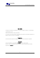
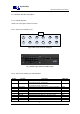
1.3.1.1. Vehicle 12 pin interface pin out
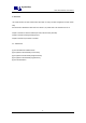
Fig 6. Vehicle 12 pin connector cable part
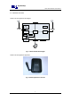
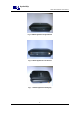
Fig 7. Vehicle 12 pin connector LOOK’ET part
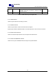
1.3.1.2. Vehicle 12 pin interface pin & cable description
Number Pin name Description Cable color
1 Digital output 1 General purpose output.500 mA max.@ 10 ~ 33V DC
To connect the vehicle, it needs Relay.
Brown
2 Digital output 2 General purpose output.500 mA max.@ 10 ~ 33V DC
To connect the vehicle, it needs Relay.
Brown
3 Analog input 1 General purpose analog input. Up to 33 V DC/10 bit resolution Yellow
4 Analog input 2 General purpose analog input. Up to 33 V DC/10 bit resolution Yellow
5 Digital input 1 General purpose input. High=10 V ~ 33 V DC, Low=0V Orange
6 Digital input 2 General purpose input. High=10 V ~ 33 V DC, Low=0V Orange
7 Digital input 3 General purpose input. High=10 V ~ 33 V DC, Low=0V Orange
8 IGNITION General purpose input. High=10 V ~ 33 V DC, Low=0V Blue
9 CANH NC. White
10 CANL NC. White
11 VIN Input power for the unit must be 12/24 volts for the unit to Red