JRVCS1 RV CONTROL AND MONITORING SYSTEM Installation and Operation Manual
JRVCS1 CONTENTS CONTENTS ................................................................................................................................. ii Introduction .................................................................................................................................. 4 Thank You! ............................................................................................................................ 4 Features ............................................................
JRVCS1 iii
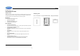
JRVCS1 INTRODUCTION Thank You! Packing List Thank you for choosing a Jensen product. We hope you will find the instructions in this owner’s manual clear and easy to follow. If you take a few minutes to look through it, you’ll learn how to 1 Cover, 2 Thumb Screws 1 Body Control Module (BCM) use all the features of your new Jensen JRVCS1 for maximum enjoyment. Features Features of Jensen JRVCS1 system include: Control four zones of lighting. Monitor all water tank levels.
JRVCS1 格式化: 字型: 粗體 INSTALLATION 格式化: 縮排: 左: 0.63 公分 It’s a good idea to read all of the instructions before beginning the installation.
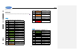
JRVCS1 24 LIGHT ORANGE SECURITY LIGHTS + (IN) (14) WIRING The wiring diagram depicts all the wiring connections required for proper operation of the unit. 25 WHITE 26 ORANGE 27 LIGHT ORANGE (14) (14) SECURITY LIGHTS - (IN/OUT) SECURITY LIGHTS + (OUT) AWNING LIGHTS + (OUT) AWNING LIGHTS - (OUT) (14) 28 LIGHT WHITE (14) DETAIL A BODY CONTROL MODULE (BCM) CONNECTIONS PIN NO.
JRVCS1 48 AUX TRIGGER 6 (OUT) 49 AUX TRIGGER 7 (OUT) 50 AUX TRIGGER 8 (OUT) 51 BROWN 52 W HITE (18) LOCKOUT SIGNAL +12V (IN) WATER HEATER GROUND (18) 53 BROWN (18) WATER HEATER ON (GAS) 54 ORANGE (18) WATER HEATER ON (ELECTRIC) 55 PINK (18) WATER HEATER FAULT 56 BLUE (14) WATER PUMP +12V (OUT) 57 WHITE (14) WATER PUMP -12V (IN/OUT) 58 BLUE (14) WATER PUMP +12V (OUT) 59 WHITE (14) AWNING 2 -12V (OUT) 60 YELLOW (14) AWNING 2 +12V (OUT) 61 WHITE (14) AW
JRVCS1 SETUP MENU LIST 8
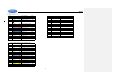
JRVCS1 ITEM GENERATOR SELECTION PROPANE OR GAS SLIDE 1 ELECTRIC OR HYDRAULIC SLIDE 2 ELECTRIC OR HYDRAULIC SLIDE 3 ELECTRIC OR HYDRAULIC SLIDE 4 ELECTRIC OR HYDRAULIC SLIDE 5 ELECTRIC OR HYDRAULIC TRIGGER 1 MOMENTARY OR LATCH TRIGGER 2 MOMENTARY OR LATCH TRIGGER 3 MOMENTARY OR LATCH TRIGGER 4 MOMENTARY OR LATCH TRIGGER 5 MOMENTARY OR LATCH TRIGGER 6 MOMENTARY OR LATCH TRIGGER 7 MOMENTARY OR LATCH TRIGGER 8 MOMENTARY OR LATCH FRONT JACKS ELECTRIC OR HYDRAULIC REAR JACKS ELECTR
JRVCS1 TROUBLESHOOTING Symptom Solution DC will not turn ON or No front panel operation Try the ON/OFF button. Check main fuse in Distribution Panel. Check 12V+ on wire to DC (RED wire). Check Ground wire to DC. Check the Red power LED is off, Check the fuse in the Distribution Panel. Check 12V+ on wire at pin 80. Check Ground wire at pin 77.
JRVCS1 SPECIFICATIONS FCC Notes Display Commander (DC) Operating Voltage . . . . . . . . . . . . . . . . . . . . . . . . . . . . . . . . . . . . . . . . . . . . . . . . . . . . . . . . 12vdc WARNING! Changes or modifications to this unit not expressly approved by the party responsible for compliance could void the user’s authority to operate the equipment. Maximum Current Draw . . . . . . . . . . . . . . . . . . . . . . . . . . . . . . . . . . . . . . . . . . . . 600ma@12vdc Minimum Operating Voltage .
SETUP Text Editing 1. Select “setup” 2.
3. A device rename window will open. Press “OK” after completing the text editing.
SETUP Scroll List Editing 1. Select “setup” 2. Press the “Δ icon before the device name and move the device to a new location, “Electric Slide 1” as an example.
SETUP Triggers 1. Triggers 1 through 8 can be added to the system.
2 Either “Momentary” or “Latch” can be selected for each Trigger.
SETUP Tanks 1.
SETUP Lights 1.
SETUP Slides 1.
SETUP Awnings 1.
SETUP Jacks 1.
SETUP Passcode 1. Select “Setup”. 2. Press “Lock” to enter passcode setup.
3. The passcode setup window will open.
3.1 Turn on Passcode Protection 3.1.1. Press “On” to turn on passcode protection. The system will request a passcode.
3.1.2. Select the idle time to activate the passcode protection.
3.1.3 Passcode protection is activated.
3.2 Turn OFF Passcode protection 3.2.1.
3.2.2. Read the passcode ”Off” disclaimer statement and press “Accept” to proceed.
3.2.3 Enter passcode to proceed 3.2.4. Passcode protection is now turned off.
3.3 Change Passcode 3.3.1. Press the “Edit” button to change to a new passcode.
3.3.2. Enter the old passcode.
3.3.3. Enter the new passcode.
3.3.4. Confirm new passcode.
DC to BCM 1. Select “Setup” 2.
3. Currently, it shows no Bluetooth Low Energy device connected to this DC. Press the “Select” button across from the “BLE Device”.
4. The DC will find and list all available devices.
5. Press the target BCM to connect, “JENSENBCM 037EA0” as an example. 6. The DC will automatically return to the previous page and show the paired BCM.
7. Press the hot key to exit the “Maintain” setup page and the DC will start to connect to the selected BCM.
BCM to DC BLE connection is activated by the DC. The BCM only needs to power up. There is no action needed from the BCM.
PAIRING INSTRUCTIONS 1. DC side. 1.1 Select “Setup”. 1.2. Select “Bluetooth”.
1.3. Currently, it shows no BT paired device connected to this DC. Press the “Discover” button to activate the BT pairing mode.
1.4. Press “Allow”.
2. Mobile Device side. 2.1 Press “Bluetooth” on the “Setup” page to find the DC device.
2.2. The Mobile APP will scan for the DC device.
2.3. Find the “DC” in the unpaired device list. Press “DC device” to pair with it.
3.2 The DC now shows the Mobile device is paired. Software Update 1. Select “Setup”.
2. Attach the update software USB Drive before selecting “Maintain”.
3. The system will look for specific file names for software updates and turn on “Select” action buttons accordingly. ‐ File name: “JRVCS1_AP Vxxxx.apk” DC APP update, (xxxx is version number) ‐ File name: “JRVCS1_CM Vxxxx.bin” BCM ‐ File name: “update.
3.1. Press the APP “Update” button to update DC APP.
3.2. Press the BCM “Update” button to update the BCM firmware.
3.3 Press the DC “Update” button to update DC Android OS.
Reset Floor Plan 1. Select “Setup”. 2. Press “Default” to restore the system to previous settings.
3. Select “Floor Plan” to restore the previous floor plan setting. Current settings will be lost.
4. Select “Factory” to restore back to ASA default settings. Current settings will be lost.
ASA Electronics Corporation www.asaelectronics.com www.jensenrvdirect.