
User's Manual
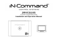

JRVCS105
5
INSTALLATION
It’s a good idea to read all of the instructions before beginning the installation. We recommend
having your Jensen JRVCS105 installed by a reputable RV dealership
Tools and Supplies
You will need these tools and supplies to install your JRVCS105:
Phillips screwdriver
#2 square drive bit
Wire cutters and strippers
Electrical tape
Volt meter/test light
Crimping tool
Fork Crimp connectors
10 gauge wire for power and slide connections
14 and 18 gauge wire for all other connections
Four #8 PH (0.164” x 0.75”) screws for the DC
Six #8 PH (0.164” x 1.0”) screws for the BCM
Disconnecting the Battery
To prevent a short circuit, be sure to turn off 12V power and remove the negative (-) battery
cable prior to installation.
Selecting the Mounting Location
Select a mounting location, taking care to avoid the following:
Places exposed to heat-radiating appliances such as electric heaters
Adjacent to other equipment that radiates heat
Under thermostats
Poorly-ventilated or dusty places
Moist or humid locations
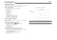
Mounting the Display Commander (DC)
Use the mounting hole diagram to measure and cut a mounting hole, allowing space
below for future programming and behind for ventilation
Route power and transmit wires through the hole and connect
Check and ensure correct operation
Mount the unit using four #8 PH (0.164” x 0.75”) screws
Attach Trim ring
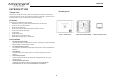
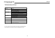
CUTOUT FOR DISPLAY COMMANDER (DC)
NOTE: Before cutting the mounting hole, make sure the area behind the mounting
location is clear of wires, fuel and vacuum or water lines; ensure there is at least a
2.75”clearance below the Display Commander to allow for programming by USB stick.
4.33
3.0