JRVCS105 RV CONTROL AND MONITORING SYSTEM Installation and Operation Manual
JRVCS105 TABLE OF CONTENTS Table of Contents ........................................................................................................................................................................................................................................................................................... 2 Introduction .......................................................................................................................................................................
JRVCS105 Software Update .......................................................................................................................................................................................................................................................................................... 24 Reset: Floor Plan ......................................................................................................................................................................................
JRVCS105 INTRODUCTION Packing List Thank You! Thank you for choosing iN-Command. We hope you will find the instructions in this owner’s manual clear and easy to follow. If you take a few minutes to look through it, you’ll learn how to use all the features of your new JRVCS105 for maximum enjoyment.
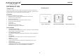
JRVCS105 INSTALLATION It’s a good idea to read all of the instructions before beginning the installation.
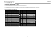
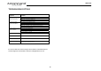
JRVCS105 WIRING TERMINAL LIST The wiring diagram depicts all the wiring connections required for proper operation of the unit. The TX (transmit) and RX (receive) wires from the BCM to DC are reversed at each device (the BCM transmits and the DC receives, and vice versa). BODY CONTROL MODULE (BCM) CONNECTIONS PIN NO. WIRE GAUGE DESCRIPTION 1 18 AWG FRESH TANK 1 (IN) PIN NO.
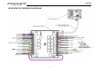
JRVCS105 BCM AND DC WIRING DIAGRAM 7
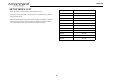
JRVCS105 SETUP MENU LIST ITEM Tanks, light groups, and motor functions can be added or removed. SELECTION Black Water Tank 2 No, Yes Gray Water Tank 2 No, Yes Grey Water Tank 3 No, Yes may not include relays for non-OEM functions. Basic automotive 1505 relays (12VDC Light Group 1 No, Yes Coil, 40/30A 14VDC Contact) can be purchased for installation and repair.
JRVCS105 SAFETY LOCKOUT IN-Command is equipped with a Safety Lockout feature to ensure certain system functions are unavailable during transit. When the Brake or Right Turn Signal on the tow vehicle is activated, IN-Command will lock down all motorized functions. A red button, with Travel Lock in white text, will appear on the DC and mobile devices will display “Travel Lock On” in red letters. All motor functions will cease to actuate and Disable will be written on their buttons.
JRVCS105 TROUBLESHOOTING Symptom Solution Display Commander (DC) will not turn ON or the touch screen will not function Press Reset Button on BCM Check main fuse in Distribution Panel. Check 12V+ on wire to DC (RED wire). Check Ground wire to DC. Try cycling power at Distribution Panel. Check if the Red power LED is off. Check the fuse in the Distribution Panel. Check 12V+ on wire at pin 35. Check Ground wire at pin 33.
JRVCS105 OVERRIDE SWITCH The Body Control Module has an override switch and knob. The knob below the switch corresponds to a motor function made by the Display Commander and Handheld Devices App. The switch and knob actuate all the motor functions on the RV. To use the override switches, locate the switch on the BCM. Turn the knob underneath the switch to select the component. Press up or down on the switch. The switch is momentary and will activate the component only while pressed in either direction.
JRVCS105 SPECIFICATIONS FCC Notes Display Commander (DC) Operating Voltage . . . . . . . . . . . . . . . . . . . . . . . . . . . . . . . . . . . . . . . . . . . . . . . . . . . . . . . . 12VDC WARNING! Changes or modifications to this unit not expressly approved by the party responsible for compliance could void the user’s authority to operate the equipment. Maximum Current Draw . . . . . . . . . . . . . . . . . . . . . . . . . . . . . . . . . . . . . . . . . . . . . . .1.
JRVCS105 PASSCODE PROTECTION A passcode is required to access the system. On first using the system, you are required to Confirm the new passcode. enter and confirm a new passcode.
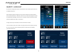
JRVCS105 MENU: 2. Long press the intended text, e.g., “Motor 1”. From the Menu screen you can: Edit IN-Command function text Reposition functions Enable/disable functions See the status of IN-Command Connect devices with Bluetooth Change the passcode Reset the floor plan And view IN-Command’s legal documents and customer support information The Setup button is used by the manufacturer. Text Editing 1. 3. A device rename window will open.
JRVCS105 Scroll List Editing Tanks 1. Push the “Pages” button twice. Black water tanks, and Gray water tanks can be added to the system. Press and hold the “≡” icon before the device name and drag to move the device to a new Lights location, “Motor 1” is shown as an example. Light Groups can be added to the system. 2.
JRVCS105 Slides Slides can be added to the system. Awnings Awnings can be added to the system.
JRVCS105 Passcode 1. Push the “Pages” button twice. 2. Press “ 3. ” to enter passcode setup. 17 To change Passcode you will need to enter the current passcode.
JRVCS105 Set Passcode Timer Press the “Set Timer” button to select the idle time to activate the passcode protection. 3. Clear Passcode Change Passcode 1. Press the “Change Passcode” button to change to a new passcode. 2. Enter the new passcode. Confirm new passcode. Press the “Clear Passcode” button to clear the passcode. This will restart the APP, take the user to the End-User License Agreement, and have the user setup a new passcode.
JRVCS105 MOBILE DEVICES: IN-Command is able to pair to Android and iOS devices using the iN-Command App. Visit the Google Play and Apple App stores on your mobile device to download and use the iN-Command App. Seven mobile devices are able to be paired IN-Command at one time, but only 1 iOS and 3 Android devices are able to be actively paired at the same time; meaning, 3 Android devices and 1 iOS device can all actively control the IN-Command functions.
JRVCS105 Pairing a Mobile Device to DC 1. On the DC: 1.1 Push the “Pages” button 2 times. 1.3 Or press “Discover” for the DC to become “visible” to other devices for 300 seconds. Press “Allow”. 1.2 Select “ ”. Press “Scan” to start scanning for unpaired devices.
JRVCS105 2. On the Mobile Device: 2.1 Press “Bluetooth” on the “Setup” page to find the DC 2.2 The Mobile APP will scan for the DC device. device. 2.3 The DC will be displayed in the Unpaired Devices list in the format “JENSENDCXXXXXX”. Press the DC device in the list to pair with it.
JRVCS105 Setting the Floor Plan on the Mobile Device 3.1 On the DC, a request message will appear. Press “Pair” to start the BT pairing and 1.1 After Pairing the mobile Device, go to the settings menu on that device and select concurrently accept the pairing on the Mobile device. “Reset”. 3.2 The DC now shows the Mobile device is paired. 1.2 Select “Floor Plan”. This will change the home screen, configure the mobile device’s buttons, and populate the function list.
JRVCS105 CHECKING FOR AN ACTIVE BLUETOOTH SESSION 1. Push the “Pages” button 2 times and select the connections, or “ “, menu. This page shows the current Actively Paired handheld devices. To disconnect a handheld device, press “Disconnect”, or simply shut down the device’s app. This function is used to disconnect a device that is not actively being used, and to allow another device to be connected.
JRVCS105 SOFTWARE UPDATE* Software updates include floorplan redesigns and app version updates. 3. The Settings menu will appear. Press the “Update” button next to the Version, or “Select” next to Floor Plan. Insert USB drive with software update into the USB port located underneath the bottom right corner of the DC. The system will look for specific file names for software updates. 1. - File name: “JRVCS1_AP Vxxxx.apk” DC APP update, (xxxx is version number) - File name: “JRVCS1_CM Vxxxx.
JRVCS105 5.2 5.1 Ensure the updated program displays correctly After the update is completed, press the “Home” button, and then return the Settings Page *If a software update is needed, go to http://www.asaelectronics.com//in-command ** The Engineering Passcode is used by the manufacturer for programming and troubleshooting purposes. Should there be a software issue, call ASA Electronics Technical Support at 1-877-845-8750 or email them at info@asaelectronics.
JRVCS105 Reset: Floor Plan 2. To reset the floor plan, removing customizations, press the “Pages” button twice. Select one of the two options to restore to a previous state. Current settings will be lost. - Floor Plan: restore to previous floor plan setting. - Factory: restore to default setting. 1. Select the Passcode page and enter the current passcode. 3. 26 Select “Floor Plan”.
JRVCS105 SYSTEM CALIBRATION* 1. Push the “Pages” button 2 times and select the Settings Menu. Enter the Engineer Passcode.** 2. Scroll to the bottom of the page and select “Admin”. 3. Enter admin passcode to proceed.** 4. Select the device that needs to be calibrated.
JRVCS105 5. Select “Tanks” to set resistor reference value for every tank. 7. To calibrate the Touch Screen, select “Set”. Follow the instructions. The DC will restart after calibration. 6. After setting the values, return to previous screen and select “OK” to save the change. *The system should be calibrated by the manufacturer and only need to be accessed for troubleshooting. ** The Administration Passcode is used by the manufacturer for programming and troubleshooting purposes.
JRVCS105 ASA Electronics Corporation www.asaelectronics.com www.jensenrvdirect.