
User's Manual


User Manual: Field Transmitter
PCU_User_Guide_1.3.0 iv © 2019 Syscor Controls & Automation Inc.
List of Figures
Figure 1 - PCU with cable-mounted sensors .................................................................................................................................... 4
Figure 2 - PCU with body-mounted sensors ..................................................................................................................................... 4
Figure 3 - PCU with rigid pipe-mounted sensor ................................................................................................................................ 5
Figure 4 - PCU with magnetic mount to pipe flange ......................................................................................................................... 5
Figure 5 - Variety of mounting options with generic bracket ............................................................................................................. 5
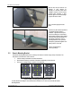
Figure 6 - Sample generic mounting bracket configuration .............................................................................................................. 6
Figure 7 - Magnetic mounting for hazardous locations ..................................................................................................................... 6
Figure 8 - U-shaped part of bracket .................................................................................................................................................. 6
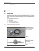
Figure 9 - Remote and directly mounted units .................................................................................................................................. 7
Figure 10 - Direct mounted PTFE tape application .......................................................................................................................... 7
Figure 11 - Inserting plug into unused gland .................................................................................................................................... 7
Figure 12 - Direct and remote sensor probe wire preparation ......................................................................................................... 7
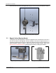
Figure 13 - PCU wiring compartment ............................................................................................................................................... 8
Figure 14 - Sensor probe wiring ....................................................................................................................................................... 8
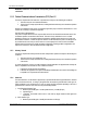
Figure 15 - Standard size battery pack ............................................................................................................................................ 9
Figure 16 - Extended size battery pack ........................................................................................................................................... 9
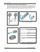
Figure 17 - Battery compartment exploded view ............................................................................................................................ 10
Figure 18 - Antenna connection ..................................................................................................................................................... 10
Figure 19 - Power and communication unit (PCU) ......................................................................................................................... 13
Figure 20 - Power and communication unit (PCU) with extended outer cover .............................................................................. 13
Figure 21 - Hydrocarbon liquid and vapor detector (HCD) ............................................................................................................. 14
Figure 22 - Hydrocarbon liquid and vapor detector with water level sensor (HCDW) ..................................................................... 14
Figure 23 - Generic mounting bracket ........................................................................................................................................... 15
Figure 24 - Magnetic mounting bracket ......................................................................................................................................... 16
Figure 25 - System wiring diagram ................................................................................................................................................. 17
Figure 26 - Cable gland ................................................................................................................................................................. 17