
User Manual


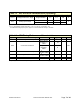


Table Of Contents

RF26X Data Sheet Document Number 430141-01A Page 7 of 14
Table 1.3. ADC Electrical Characteristics (Operating)
Symbol
Parameter
Condition
Min
Typical
Max
Unit
V
REFH
3
Voltage Reference, High Programmable 1.5 1.6 1.8 V
V
INDC
Analog input voltage
Single Ended 0 1.8
V
Differential
4
0 3.3
3
V
REFH
is programmable to three fixed values; 1.5V, 1.6V, and 1.8V. The default is 1.6V.
4
Each differential analog input may be as high as 3.3V but the differential voltage is still limited.
Table 1.4. ADC Timing/Performance Characteristics
Symbol
Parameter
Condition
Min
Typical
Max
Unit
R
AS
Source impedance at input
5
3k
kΩ
RES Conversion Resolution
Single Ended
CLKADC <=
4MHz
10
Bits
Single Ended
CLKADC >
8MHz
8
DNL Differential non-linearity
V
REFH = 1.6V
CLKADC=4MHz
-0.5 LSB
INL Integral non-linearity
V
REFH = 1.6V
CLKADC=4MHz
0.8 LSB
E
ZS
Zero-scale error
1.5
LSB
E
G
Gain error
1
LSB
5
Any analog source with a source impedance greater the 3kΩ will increase the sampling time.