
User's Manual
6
Step 6: If necessary, drill a hole large enough for the connector on the RFID Extension
Cable to fit through, usually in a wire chase.
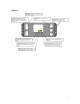
Step 7: Plug one end of the RFID Extension Cable into one of the AIM2 Main Module’s
Tank Ring Ports (Fig. 1).
Step 8: Place the provided rubber grommet around the RFID Extension Cable and pass
the cable through the drilled hole, fitting the grommet securely in the opening.
Step 9: Route the RFID Extension Cable to the top of the fuel tank filler neck. If routing
outside the vehicle, make sure to use the protective loom for the entire length of the pull
under the vehicle. Loosely zip tie the loom and cable. Make sure to leave room to adjust
slack.
Note:
Please make sure cables and wires are routed away from moving components or
devices that may become hot during normal vehicle operation.
Step 10: Drill hole large enough for the connector on the Filler Neck Ring in the housing
around the filler neck where the gas cap is located.
Step 11: Place the Filler Neck Ring around the filler neck under the gas cap and pass the
Filler Neck Ring cable (with grommet) through the drilled hole and secure grommet in
opening.
Step 12: Attach RFID Interface Module to Filler Neck Ring cable and RFID Extension
Cable. Ensure that the connections are sealed and the gaskets fully compressed and zip
tie in place.
Step 13: From the mounting location of the AIM2 Main Module, pull the slack from the
RFID Extension Cable so that it is snug.
Step 14: Tighten all zip ties and clip the extra plastic with a pair of wire snips and seal
both drilled holes with silicon.
Step 15: Coil any leftover slack from the RFID Extension Cable secure so it is out of the
way.
Step 16: You may now connect the AIM2 Main Module to the Analog Speed Sensor
Cable Assembly via the Power/Speed Sensor Port (Fig. 1). Verify that the power LED is
illuminated and the module is ready for programming.