
User's Manual

5
AIM2 vehicle installations for vehicles using the Vehicle Speed Sensor
(odometer) output.
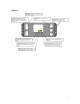
Step 1: Select mounting location for the AIM2 Main Module. Recommended locations
are under the dash or under the seat that is on the same side of the vehicle as the fuel
tank’s filler neck. Keep in mind the distance from the power source and grounding
requirements in relation to the mounting location.
Note:
The AIM2 Main Module should be mounted out of harms way but, accessible for service
or troubleshooting.
Warning:
The AIM2 Main Module uses Radio Frequency technology to communicate with the fuel
island. Do not mount this unit in steel or fiberglass enclosures. This type of install may
prevent your system from working properly.
Please contact FuelMaster for installation recommendations.1-800-888-9136
Step 2: Connect the Analog Speed Sensor Cable Assembly ground wires as well as the
main ground lug to a good chassis ground. For the main ground lug, use 12 gauge wire
and the provided 12 gauge ring terminal.
Note:
Do not lengthen these wires. It may be necessary to remove paint from painted surfaces
to achieve a proper ground.
For installations in Canada, 2 12 gauge ground wires must be used.
Do not connect the AIM2 at this time.
Step 3: Locate a constant +12VDC supply with the vehicle key in the “off “ position.
This will provide power to the “RED” lead of the Analog Speed Sensor Cable Assembly
to operate the AIM2 Main Module.
Step 4: Locate a switched +12VDC supply that is present only when the vehicle key is in
the “ON” position. Connect the “BROWN” wire of the Analog Speed Sensor Cable
Assembly to this source. This signal is required to indicate the status of the vehicle on or
off.
Step 5: Locate and terminate the GREEN wire of the Analog Speed Sensor Cable
Assembly to the VSS (vehicle speed sensor) output. This signal can be found at the
transmission speed sensor after the vehicles computer module.
Note:
Vehicle applications may vary with manufacturer and model.