
User's Manual


32
Appendix A: Table of Figures
This appendix shows the figures that are used throughout the manual and
the pages they can be found on.
Throughout this manual, there are screenshots and figures used as examples of the user
interface. This appendix contains a list of those figures and the pages where they can
be located.
If you are in need of more support or have a question that is not contained in this
manual, please contact Fuel Master’s industry leading help desk at (800) 888-9136 ext.
252 with any questions you may have.
Figure 1 – Truck Interface Module (TIM).......................................................................... 9
Figure 2 – TIM LED’s and Antenna plug......................................................................... 10
Figure 3 – TIM with Mounting Bracket ........................................................................... 11
Figure 4 – Mounting bracket............................................................................................. 11
Figure 5 – TIM Components............................................................................................. 12
Figure 6 – UIT Front Panel............................................................................................... 13
Figure 7 – UIT – Bottom Panel Components ................................................................... 14
Figure 8 – Right-side Panel Components ......................................................................... 15
Figure 9 – Vehicle-Charging Cradle................................................................................. 16
Figure 10 – Desktop Download/Charging Cradle ............................................................ 17
Figure 11 – External Battery Pack.................................................................................... 17
Figure 13 – ADC Receipt Printer...................................................................................... 19
Figure 14 – Uni-Directional Pulser................................................................................... 20
Figure 15 – Bi-Directional Pulser..................................................................................... 20
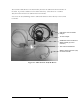
Figure 16 – Thermal Temperature Sensor........................................................................ 21
Figure 17 – Temperature Probe Assembly ....................................................................... 21
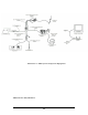
Illustration 3. - ADC System Component Equipment...................................................... 25
Figure 18 – ADC Gumstix TCP Router............................................................................ 26
Illustration 4. - ADC PC/RF Installation .......................................................................... 29