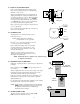
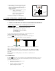
VISUAL HEADLAMP ALIGNMENT SYSTEM With: “Visual Assist” Meter VISUAL ASSIST SELECTOR “HIGH” BEAM “LOW” BEAM ASSEMBLY OPERATION CALIBRATION 524 SE Transport Drive Lees Summit, MO 64081 Safety by Design 888-884-8182 816-525-926 FAX: 816-525-9283 www.symtechcorp.
INDEX 1. GENERAL Pg. 3 1.1 1.2 1.3 1.4 “LCA 2EZ” INTRODUCTION SYSTEM COMPONENTS LASER WARNING “VISUAL ASSIST” METER & SWITCH 2. ASSEMBLY Pg. 4 2.1 2.2 2.3 2.4 2.5 2.6 BASE / WHEEL ATTACHMENT MAST / GLIDE PLATE / ROTATIONAL MAST MOUNT OPTICAL ALIGNMENT HEAD SIGHTING UNIT SIGHTING UNIT CALIBRATION FLOOR SLOPE LASER 3. OPERATION Pg. 6 3.1 ALIGNMENT BAY(s) PREPARATION 3.2 FLOOR SLOPE MEASUREMENT 3.3 VEHICLE PREPARATION, Prior to Alignment 4. HEADLAMP ALIGNMENT PG. 7 4.
1. GENERAL 1.1 INTRODUCTION The Model “LCA 2EZ” Visual Headlamp Alignment System is an economical optical alignment tool that functions under the same principle for accuracy and dependability of an aiming screen, with the added benefit of a “Visual Assist” meter, without the excessive use of valuable shop space and the confusion of vertical and horizontal lamp placement. System design and operation has been engineered with the technician in mind.
1.4 VISUAL ASSIST METER & SWITCH The “Visual Assist” meter is an aide for positioning the headlamp pattern to its correctly designed position. While visually adjusting the headlamp into position, the “Visual Assist” meter will raise in numeric reading if adjustment is directed in the correct direction. Adversely, the meter reading will decrease if headlamp is adjusted in the incorrect direction.
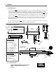
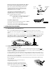
2.3 OPTICAL ALIGNMENT HEAD Remove optical alignment head from shipping carton. Inspect for any damage that may have occurred during shipment i.e. lens, case, etc.. Attach optical alignment head to the mast glide plate by aligning mounting holes of glide plate with the holes in the optical head.
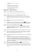
The laser is used for floor slope measurement only. Remove laser after floor slope measurements have been recorded Remove floor slope laser from packaging and insert front fixture placement pin into hole on top and at front of the optical head, also there is an indentation provided for the height adjustment screw to rest within.
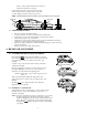
wheels, to achieve equal measurements, more than one eccentric axle change may be required. Note the number on the floor slope gauge and record that number along with the bay designate on floor slope sticker provided. Repeat procedure for other bays and record. NOTE: After measurements have been taken, remove laser and store in a secure place MEASURE MEASURE 3.3 VEHICLE PREPARATION Remove ice or mud from under the fenders.
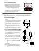
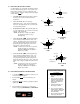
4.3 SELECTING HEADLAMP PATTERN V Not all headlamps are created alike and different vehicles may have different design patterns. To be certain of the lamp pattern, a designate is located on the lamp at the bottom of the lens. Patterns of lamps that may be aligned with the LCA 2EZ are; H SAE HIGH BEAM: All high beam lamps. Highest intensity point is centered on the Horizontal / Vertical axis. SAE LOW BEAM: All low beam lamps manufactured prior to 1999, selective manufacture after 1999.
While viewing aim screen and “Visual Assist” meter, adjust headlamp to position that appears as graphic illustration of headlamp pattern selected and “Visual Assist” meter has reached its highest achievable reading for that lamp. NOTE: Graphics on aiming screen denote position of lamp position in inches. 8 inches H H Outer box denotes 8 inches, inner box denotes 4 inches. Each hash mark denotes 1 inch increment. Repeat steps 2 through 4 for remaining lamps. 4 inches V 6.
Check all other mounting screws, bolts and nuts for tightness. Clean the mast area where the brake rides with a mild detergent to assure of secure holding. Clean the front lens, sighting unit and viewing window with a mild detergent being careful to use a non-abrasive soft cloth. 6. FREQUENTLY ASKED QUESTIONS Question: Level in optical head is not centered during alignment procedure? Answer: Level vial is used ONLY when checking the calibration of the floor slope laser.
Question: Can the “Visual Assist” meter measure light intensity? Answer: The “Visual Assist” meter DOES NOT MEASURE LIGHT INTENSITY. It assists in locating the highest value reading of that particular lamp. If a light intensity meter is an instrument your facility would like to procure, SYMTECH offers the “AIM 200”, a hand held, self-contained precision instrument specifically designed for measuring automotive light intensities.