With LINE LASER ALIGNMENT ELECTRONIC HEADLAMP ALIGNMENT SYSTEM ASSEMBLY CALIBRATION OPERATION REV 4/30/2012 524 S. E. Transport Drive Lee’s Summit, Missouri 64081 888-884-8182 816-525-9263 FAX: 816-525-9283 www.symtechcorp.
INDEX 1. GENERAL Pg. 5 1.1 1.2 1.3 2. SYSTEM COMPONENTS Pg. 65 2.1 2.2 2.3 2.4 2.5 2.6 2.7 3. CONTROL PANEL 2.1.1 ADJUSTMENT SELECTION BUTTON 2.1.2 ON/SELECT BUTTON 2.1.2.1 POSITION CHECK/BATTERY CHARGER LEVEL 2.1.2.2 HEADLAMP BEAM SELECTION 2.1.3 INTENSITY CHECK + BATTERY CHARGER METER 2.1.3.1 READING INTENSITY AND BATTERY CHARGER METERVEHICLE ALIGNMENT LINE LASER 2.1.4 LAMP POSITION INDICATOR ARROWS 2.1.5 BATTERY CHARGER SOCKET 2.1.5.1 BATTERY PACK ALIGNMENT HEAD 2.2.1 OPTICAL HEAD 2.2.
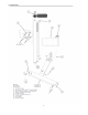
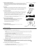
1.1 GENERAL ASSEMBLY INSTRUCTIONS Step 1 Install Front Eccentric Axle assembly (eccentric without scale) into front of wheel base until small scribe mark aligns with indicator arrow on base. Tighten mounting screws. 1. Rotate eccentric axle Step 2. Install Floor Slope Eccentric Axle assembly (attached indicator scale & handle) into rear of wheel base Tighten mounting screws. 2 Step 3. Install non-eccentric wheel 3 Place flat washer on 5/16”-18 x 2.5” bolt and push bolt through hole inside of base.
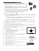
2.0 SYSTEM COMPONENTS 3 2.1 CONTROL PANEL The CONTROL PANEL consists of FIVE areas of interest. 1. 2. 3. 4. 5. ADJUST SELECTION MODE BUTTON ON/SELECT BUTTON INTENSITY CHECK + BATTERY CHARGE METER LAMP POSITION INDICATOR ARROWS BATTERY CHARGER SOCKET 4 5 2.1.1 ADJUSTMENT SELECTION BUTTON When a beam type is selected by pushing the ON/SELECT button the Audit Adjustment LED will turn on indicating that the aimer is in Audit adjustment mode.
3 When auditing the headlamp, the arrows indicate if the lamp is within or out of allowable limits of +/- 4 inches. 2.1.5 BATTERY CHARGER SOCKET The HBA 5 is powered by an internal battery supply that will provide a sufficient amount of power during working hours. An 110V ac power supply adapter is provided with the system for charging. A red LED light labeled “Charge” lights up to inform the operator that the battery is receiving power and is charging. 2.1.5.
2.4.3 WHEELS TO WHEELBASE MOUNTING Mounting Bolt There are three wheels on the wheelbase. Two wheels have an axle block that allows them to fit inside the wheelbase, and be adjusted. Each axle block has two bolts, one for mounting to the wheelbase, and a second for clamping the wheel axle into the block. The eccentric wheel is installed on the right leg of the wheelbase. The straight shaft wheel is applied to the left leg of the wheelbase.
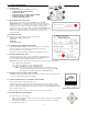
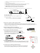
4. 5. 6. 7. 8. 9. 10. Install laser on top of alignment head placing position pin in hole located in center of bezel Turn on the laser. Move to the front wheel area of the vehicle With tape measure, measure from floor to where laser beam intersects measuring device. Note this measurement. Move to rear wheel area of vehicle and measure from floor to laser beam. Note this measurement. Adjust alignment head so that laser beam is the same height at both front and rear wheel positions.
NOTE: When positioning the alignment head take caution not to rotate the alignment head out of position as determined by the line laser . 3.5 HEADLAMP ALIGNMENT The purpose of headlamp alignment is to align the vehicle headlamp such that the driver of the vehicle has the most effective lighting of the road and its conditions, while still being safe for both the driver and oncoming traffic. 3.5.
2. Measure height of laser beam at both front and rear wheels using a tape measure. 3. Adjust rear eccentric wheel so that the height of the laser is equal at both front and rear wheels of vehicle. 5. Place the HBA 5 at center of vehicle. Rotate alignment head perpendicular to vehicle using mounted line laser assembly and two common points on vehicle. 6. PRESS the ON/SELECT Button. Confirm the LED next to “Position Check” on control panel is lit. 5.
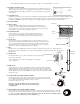
NOTE: FLOOR SLOPE LASER IS CALIBRATED AT FACTORY, CALIBRATION IS REQUIRED ONLY IN THE EVENT OF TAMPERING WITH ADJUSTMENT SCREW OR ASSURANCE OF LASER ACCURACY. Step 1: Move the HBA 5 to a level floor surface with a recommended six feet (very minimum of four feet) of unobstructed floor in front of the alignment head. Step 2: Level the alignment head. Noting the level vial on top of the alignment head, adjust the rear wheel up or down until the vial bubble is perfectly centered.
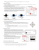
• Switch lamp to LOW BEAM mode and visually observe placement of low beam on rear alignment screen of HBA 5. Pattern should be in a relative position of alignment and appear as pictorial. Q: The lights keep blinking on the control panel, what does this mean? A: Continue blinking of the lights on the control panel indicates either the internal battery requires charging, or that the system is not in front of a light pattern. It will require twelve (12) hours to full charge battery in system.
WARRANTY All Symtech Corporation products are warranted to be free from defects in material and workmanship under normal user service for a period of one year after the sale of the product. Exception to this policy will be individually evaluated and must be approved by Symtech Corporation. The sole obligation under this warranty shall be to repair, or replace any defective product, or parts thereof, which upon examination are deemed to the seller’s satisfaction to be defective.