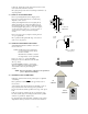
Color VISUAL HEADLAMP ALIGNMENT SYSTEM With: “Visual Assist” Meter and “Line Laser” Alignment VISUAL ASSIST SELECTOR “HIGH” BEAM “LOW” BEAM ASSEMBLY OPERATION CALIBRATION 524 S.E. Transport Drive Lees Summit, MO 64081 888-884-8182 816-525-9263 FAX: 816-525-9283 www.symtechcorp.
INDEX 1. GENERAL Pg. 3 1.1 1.2 1.3 1.4 1.5 1.6 “CVA 3EZ” ISOColor INTRODUCTION SYSTEM COMPONENTS LASER WARNING EXPOSURE TO DIRECT SUNLIGHT WARNING “VISUAL ASSIST” METER & SWITCH ISOColor LAMP PATTERN DEFINITION 2. ASSEMBLY Pg. 4 2.1 2.2 2.3 2.4 2.5 2.6 BASE / WHEEL ATTACHMENT MAST / GLIDE PLATE / ROTATIONAL MAST MOUNT OPTICAL ALIGNMENT HEAD VEHICLE ALIGNMENT LINE LASER LINE LASER CALIBRATION FLOOR SLOPE LASER 3. OPERATION Pg. 6 3.1 ALIGNMENT BAY(s) PREPARATION 3.2 FLOOR SLOPE MEASUREMENT 3.
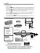
1. GENERAL 1.1 INTRODUCTION The Model “CVA 3EZ” ISOColor Visual Headlamp Alignment System is an economical optical alignment tool that functions under the same principle for accuracy and dependability of an aiming screen, with the added benefit of Color Defined Lamp Pattern and a “Visual Assist” meter, without the excessive use of valuable shop space and the confusion of vertical and horizontal lamp placement. System design and operation has been engineered with the technician in mind.
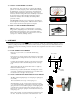
1.5 VISUAL ASSIST METER & SWITCH The “Visual Assist” meter is an aide for positioning the headlamp pattern to its correctly designed position. While visually adjusting the headlamp into position, the “Visual Assist” meter will raise in numeric reading if adjustment is directed in the correct direction. Adversely, the meter reading will decrease if headlamp is adjusted in the incorrect direction.
locking nut. Tighten nut securely then back-off ¼ turn, or until mast rotates freely with minor resistance. Move glide plate up and down the mast through its full motion, by depressing handle. 2.3 OPTICAL ALIGNMENT HEAD Remove optical alignment head from shipping carton. Inspect for any damage that may have occurred during shipment i.e. lens, case, etc.. Attach optical alignment head to the mast glide plate by aligning mounting holes of glide plate with the holes in the optical head.
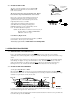
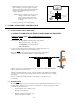
2.6 On / Off Knob FLOOR SLOPE LASER Level Adjuster Set Screw The floor slope laser assembly is factory calibrated, DO NOT turn the level adjustment set screw which is at the back of laser assembly. Fixture Placement Pin The laser is used for floor slope measurement only.
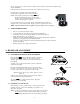
Move to the center point of the rear wheel of vehicle and measure the point where the laser strikes the tape measure, RECORD. If the measurements at the front and rear wheels are not equal, the bay has a slope. Rotate the floor slope handle on rear wheel until equal measurements are registered at the front and rear wheels.
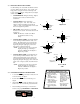
4.3 SELECTING HEADLAMP PATTERN Not all headlamps are created alike and different vehicles may have different design patterns. To be certain of the lamp pattern, a designate is located on the lamp at the bottom of the lens. Patterns of lamps that may be aligned with the CVA 3EZ are; • • • • • V SAE HIGH BEAM: All high beam lamps. Highest intensity point is centered on the Horizontal / Vertical axis. SAE LOW BEAM: All low beam lamps manufactured prior to 1999.
• While viewing aim screen and “Visual Assist” meter, adjust headlamp to position that appears as graphic illustration of headlamp pattern selected and “Visual Assist” meter has reached its highest achievable reading for that lamp. NOTE: Graphics on aiming screen denote position of lamp position in inches. Outer box denotes 8 inches, inner box denotes 4 inches. Each hash mark denotes 1 inch increment. • 8 inches H H 4 inches V Repeat steps 2 through 4 for remaining lamps. 6.
• Check all other mounting screws, bolts and nuts for tightness. • Clean the mast area where the brake rides with a mild detergent to assure of secure holding. • Clean the front lens, sighting unit and viewing window with a mild detergent being careful to use a non-abrasive soft cloth. 6. FREQUENTLY ASKED QUESTIONS Question: Level in optical head is not centered during alignment procedure? Answer: Level vial is used ONLY when checking the calibration of the floor slope laser.
Answer: The meter does not have batteries, power is provided by the light of the headlamp. Question: Is there a calibration procedure for the “Visual Assist” meter? Answer: NO calibration of meter is required. WARRANTY All Symtech Corporation products are warranted to be free from defects in material and workmanship under normal user service for a period of one year after the sale of the product. Exception to this policy will be individually evaluated and must be approved by Symtech Corporate.