
User's Manual
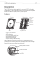
Table Of Contents

6
AP 300 Quick Reference Guide FINAL.Not for distribution.
2. Using the arrows on the bottom edge of the back of the case as
guides, move the edge to the midline of the mounting area and
mark points on the midline for the screws.
3. At each point, screw in the self-tapping screws and stop where the
threads meet the shank or shoulder of the screw.
4. If required, install the recommended safety cable—steel with a
diameter at least .15cm (.06in.)—and a security cable, and attach
them to the unit.
5. Place the middle of each of the case’s mount slots over the screw
heads.
6. Slide the case down along the mounting surface to hang the
case’s slots on the screw heads.
7. Plug the Ethernet cable into the LAN port.
8. Verify the unit has power by observing that the LEDs are lit or
flashing.
Suspended Ceiling T-Bar Mount
In this procedure, hold and twist the AP 300 on a T-bar of a suspended
ceiling grid, clicking the case into place.
Hardware
• A CAT-5 cable connected to a compatible Symbol wireless
switch—for example, the WS 2000 or WS 5000—with sufficient
slack and without a molded or integrated strain relief on the
connector to the AP 300
• Safety cable (recommended)
• Security cable (optional)
Procedure
1. If required, install the recommended safety cable—steel with a
diameter at least .15cm (.06in.)—to the safety cable tie point and
a security cable to the unit’s lock port.
2. Plug the Ethernet cable into the LAN port.
3. Face the bottom of the T-bar with the back of the case.
4. Orient the case by its length and the length of the T-bar.
5. Rotate the case in place 45 degrees counter-clockwise, or about
10 o’clock.