
User's Manual

4
AP 300 Quick Reference Guide FINAL.Not for distribution.
The AP 300 receives power through the Ethernet cable, optionally
connected to a Port Power Injector—for example, Symbol Model AP-
PSBIAS-T-12-AF Power Injector 12 Port. See the Symbol web site for
available PoE devices.
Review installation plans to determine device placement and cable
routing.
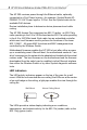
The AP 300 Access Port comprises two 802.11 radios: an 802.11b/g
radio operating in the 2.4 to 2.5Ghz band and an 802.11a radio operating
in the 4.9 to 5.875Ghz band. Each radio has an embedded controller
which runs local firmware used to perform the functions of the lower
802.11 MAC. All upper MAC functions and MAC management are
controlled by the Wireless Switch.
Motherboard firmware enables the AP 300 to boot after either a power
up or a watchdog reset. After self-boot, the motherboard sends an “I am
alive” message into the network to be adopted and loaded with the actual
runtime code. The boot firmware on the motherboard and the firmware
downloaded from the switch can be modified via the Ethernet interface
from either the Wireless Switch or by other Symbol diagnostic software
tools.
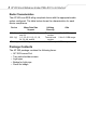
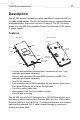
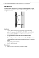
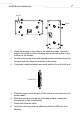
LED Indicators
The LED activity indicators appear on the top of the case for a wall
mount. With the unit mounted above a ceiling, the LEDs are at the center
of an oval badge on the ceiling; a light pipe enables the view through the
ceiling tile.
The LEDs provide a status display indicating error conditions,
transmission, and network activity for the 802.11a (amber) radio or the
802.11b/g (green) radio.
LEDs
LEDs
Above Ceiling MountWall Mount